Delta Electronics Extension Digital I/O Module DOP-EXIO14RAE User Manual
Page 71
Appendix C Use of Basic Instructions|DOP-EXIO Series
C-6
Revision March, 2008, Doc. Name: 2007PDD23000014
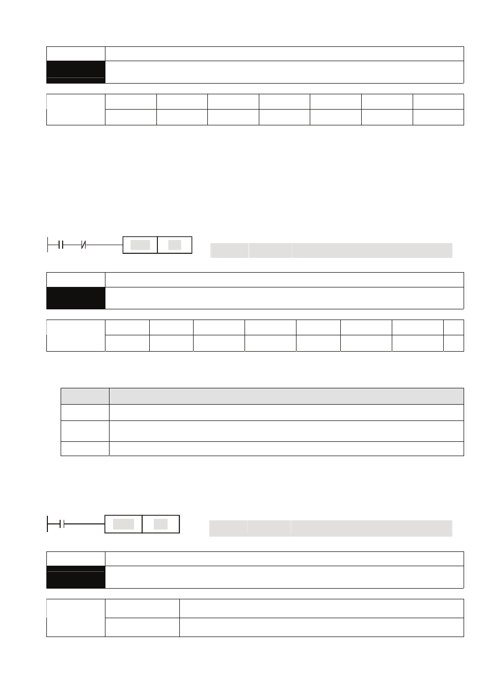
Mnemonic Functions
SET
Latch (ON)
X0~X17 Y0~Y17
M0~M1279
S0~S127
T0~T127 C0~C254
D0~D599
Operand
-
9
9
9
- - -
Explanations:
When the SET instruction is driven, its designated device will be “On” and keep being On both when
SET instruction is still being driven or not driven. Use RST instruction to set “Off” the device.
Program Example:
Ladder diagram:
Instruction code:
Operation:
LD
X0
Loading in contact A of X0
ANI
Y0
Connecting to contact B of Y0 in series
X0
Y0
Y1
SET
SET
Y1
Y1 latched (On)
Mnemonic Functions
RST
Clear the contact or the registers
X0~X17
Y0~Y17 M0~M1279
S0~S127
T0~T127
C0~C254 D0~D599 E,
F
Operand
-
9
9
9
9
9
9
9
Explanations:
1. When the RST instruction is driven, the actions of the designated devices are:
Device
Status
Y, M, S,
Coil and contact will be set to “Off”
T, C
Present values of the timer or counter will be set to “0”, and the coil and contact will be
set to “Off”
D, E, F
The content will be set to “0”.
2. If RST instruction is not being executed, the status of the designated device will stay intact.
Program Example:
Ladder diagram:
Instruction code:
Operation:
LD
X0
Loading in contact A of X0
X0
Y5
RST
RST
Y5
Resetting contact Y5
Mnemonic Functions
TMR
16-bit Timer
T-K
T0~T127, K0~K32,767
Operand
T-D
T0~T127, D0~D599