Delta Electronics Extension Digital I/O Module DOP-EXIO14RAE User Manual
Page 32
Chapter 3 Creating and Editing Programs|DOP-EXIO Series
Revision March, 2008, Doc. Name: 2007PDD23000014
3-11
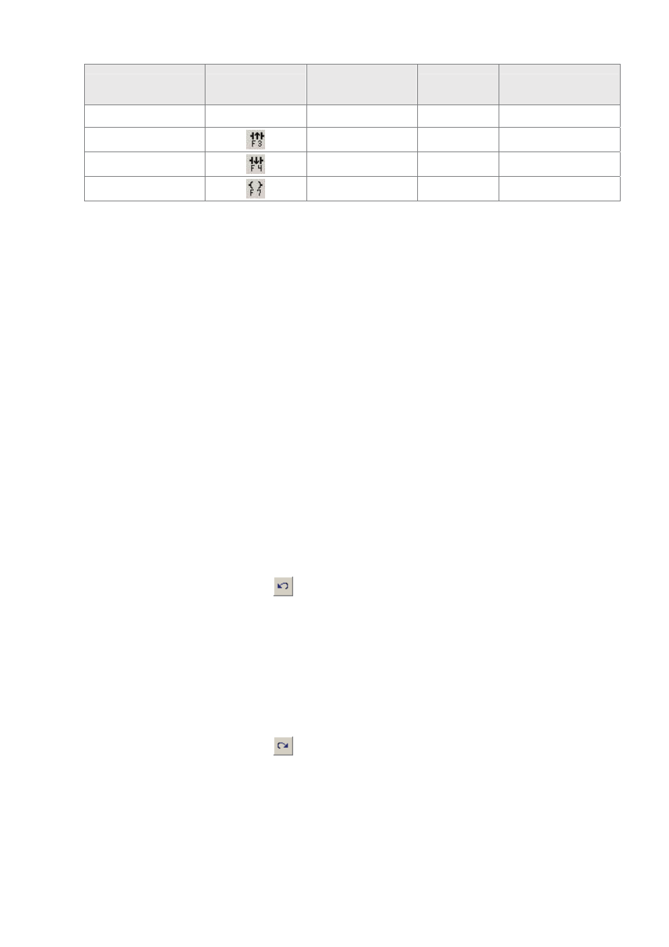
Explanation
Instruction Icon
Instruction Code
(Mnemonic Code)
Brevity Code
Example
contact
Rising pulse
LDP
+
LDP M0 or + M0
Falling pulse
LDF
–
LDF M0 or – M0
Output coil
OUT
O
OUT M0 or O M0
)
Insert / Replace Mode
Using the “Insert” key on the keyboard can switch to the Insert Mode or the Replace Mode
when editing a ladder diagram.
If the “Replace” word is displayed on the status bar, pressing the Insert key on the
keyboard is to switch to the Insert Mode. In the Insert Mode, insert a new ladder
diagram to where the editing block is located, and the original ladder diagrams
following the new diagram will shift one space to the right.
If the “Insert” word is displayed on the status bar, pressing the Insert key on the
keyboard is to switch to the Replace Mode. In Replace Mode, inserting a new ladder
diagram can replace the original ladder diagram located in the editing block, and the
following other ladder diagrams will not be changed.
)
Edit(E)
Undo(U) Ö Undo the most recent actions (the system allows the user to perform undo
action for max. 10 times)
Method 1: Click “Edit(E)” > “Undo(U)”.
Method 2: Click the icon
on the toolbar.
Method 3: Use keyboard shortcuts by pressing keys (Ctrl) + (Z).
Method 4: Right click the mouse to get a pop-up menu and select “Undo” in the
pop-up menu.
Redo(R) Ö Redo the undo action.
Method 1: Click “Edit(E)” > “Redo(R)”.
Method 2: Click the icon
on the toolbar.
Method 3: Use keyboard shortcuts by pressing keys (Ctrl) + (Alt) + (Z).
Method 4: Right click the mouse to get a pop-up menu and select “Redo” in the
pop-up menu.