Delta Electronics Extension Digital I/O Module DOP-EXIO14RAE User Manual
Page 122
Appendix D Use of Application Instructions|DOP-EXIO Series
Revision March, 2008, Doc. Name: 2007PDD23000014
D-41
Mnemonic
Operands Function
OR
D
S
1
S
2
D
Logical Word OR
Bit Devices
Word Devices
X Y M S K H
KnX
KnY
KnM KnS
T
C
D
E
F
S
1
S
2
D
y
Note:
1. If
S
1
, S
2
and D are used in device F, only 16-bit instruction is
applicable.
16-bit instruction (7 Steps)
WOR
Continuous
execution
32-bit instruction (13 Steps)
DOR
Continuous
execution
y
Flags: None
Operands:
S
1
: Source data device 1
S
2
: Source data device 2
D
: Operation result
Explanations:
1. This instruction conducts logical OR operation of S
1
and S
2
and stores the result in D.
2. Operation rule: The corresponding bit of the operation result in D will be “1” if any of the bits in S
1
or S
2
is “1”.
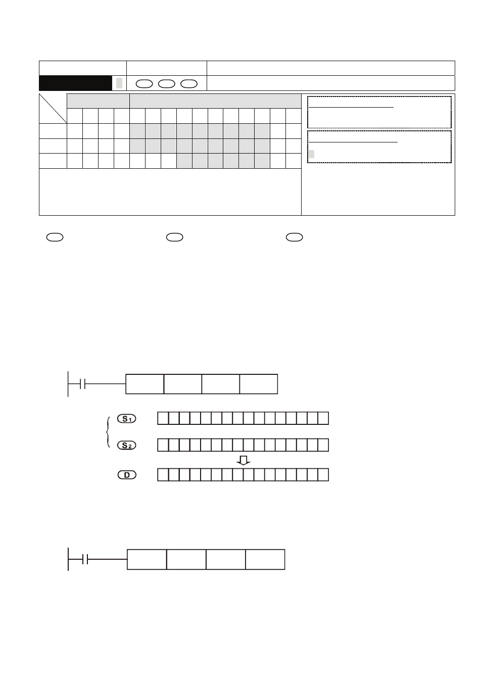
Program Example 1:
When X0 = On, the 16-bit D0 and D2 will perform WOR, logical OR operation, and the result will be
stored in D4.
X0
WOR
D0
D2
D4
0
0
1
1
1
1
1
1
0 0 0
0
0
0
1
1
1
1
0
0
0
0
1
1
1
WOR
b15
b0
0
0
0
0
0
0
1
1
0
1
1 1
0
1
1
1 1
1 1 1 1 1
1
Before
execution
After
execution
D2
D4
D0
Program Example 2:
When X1 = On, the 32-bit (D11, D10) and (D21, D20) will perform DOR, logical OR operation, and the
result will be stored in (D41, D40).
X1
DOR
D10
D20
D40