Delta Electronics Extension Digital I/O Module DOP-EXIO14RAE User Manual
Page 156
Appendix D Use of Application Instructions|DOP-EXIO Series
Revision March, 2008, Doc. Name: 2007PDD23000014
D-75
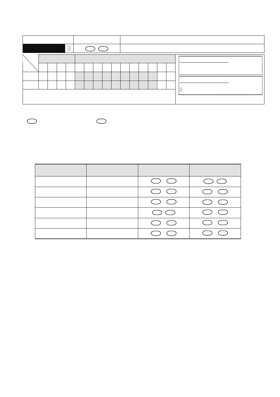
Mnemonic
Operands Function
OR※
D
S
1
S
2
Contact Logical operation OR※
Bit Devices
Word Devices
X Y M S K H
KnX
KnY
KnM KnS
T
C
D
E
F
S
1
S
2
y
Note: :
=
※
, >, <, <>, ≦, ≧
16-bit instruction (5 Steps)
OR※
Continuous
execution
- -
32-bit instruction (9 Steps)
DOR※
Continuous
execution
- -
y
Flags: None
Operands:
S
1
: Data source device 1
S
2
: Data source device 2
Explanations:
1. This instruction compares the content in S
1
and S
2
. If the result is not “equal”, the continuity of
the instruction is enabled. If the result is “equal”, the continuity of the instruction is disabled.
2. OR※ (=, >, <, <>, ≦, ≧) instruction is used for direct connection with BUS.
16 -bit instruction
32 -bit instruction
Continuity condition
No-continuity
condition
OR=
D
OR=
S
1
=
S
2
S
1
≠
S
2
OR>
D
OR>
S
1
>
S
2
S
1
≦
S
2
OR<
D
OR<
S
1
<
S
2
S
1
≧
S
2
OR<>
D
OR<>
S
1
≠
S
2
S
1
=
S
2
OR<=
D
OR<=
S
1
≦
S
2
S
1
>
S
2
OR>=
D
OR>=
S
1
≧
S
2
S
1
<
S
2
3. If the most left bit of S
1
and S
2
(16-bit instruction: b15、32-bit instruction: b31) is “1”, the compare
value will be regarded as the negative value for comparison.
4. When 32-bit counters (C200 ~) are used in this instruction for comparison, make sure to adopt
32-bit instruction (DOR※). If 16-bit instructions (OR※) is adopted, a “program error” will occur
and the ERROR indicator on the panel will flash and the connecting controller can not run..
Program Example:
1. When X1 = On, or the value of C0 is equal to the value of K200, Y10 = On.
2. When X2 and M30 are both, or the value of 32-bit data (D101, D100) is equal to or higher than
K100,000, M60 = On.