3 ladder diagram editing explanation, 3 ladder diagram editing explanation ) – Delta Electronics Extension Digital I/O Module DOP-EXIO14RAE User Manual
Page 31
Chapter 3 Creating and Editing Programs|DOP-EXIO Series
3-10
Revision March, 2008, Doc. Name: 2007PDD23000014
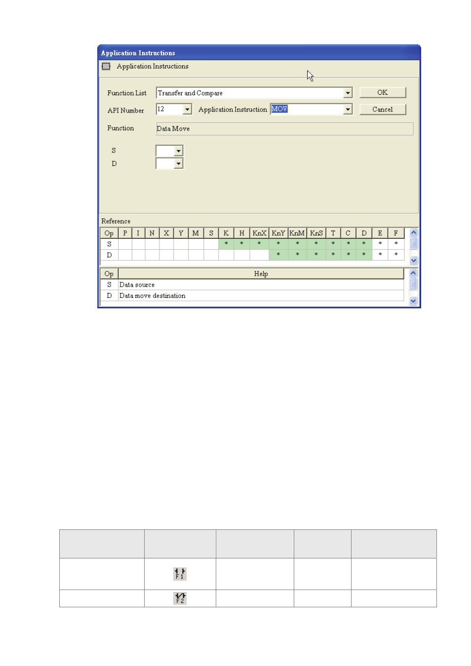
4. Input device name in the field of “S” (Operand 1) and “D” (Operand 2), and input
device number in the field of “Device Number” in order. Select index register E or
F if it exists. Then, press the “OK” button to save the settings.
5. The user can also double click the mouse on the “@” or “*” symbol in the device
reference table (refer to the figure above) to designate the device name (The
symbol @ indicates this device can be modified by index register E or F and the
symbol * indicates this device can not be modified by index register E or F).
3.3
Ladder Diagram Editing Explanation
)
Keyboard Entry
HMI-WPLSoft provides several brevity codes for the user to input Instructions more quickly
and conveniently when editing a ladder diagram. Please refer to the following table.
Explanation
Instruction Icon
Instruction Code
(Mnemonic Code)
Brevity Code
Example
Normally open
contact
LD
A
LD M0 or A M0
Normally closed
LDI
B
LDI M0 or B M0