Delta Electronics Extension Digital I/O Module DOP-EXIO14RAE User Manual
Page 147
Appendix D Use of Application Instructions|DOP-EXIO Series
D-66
Revision March, 2008, Doc. Name: 2007PDD23000014
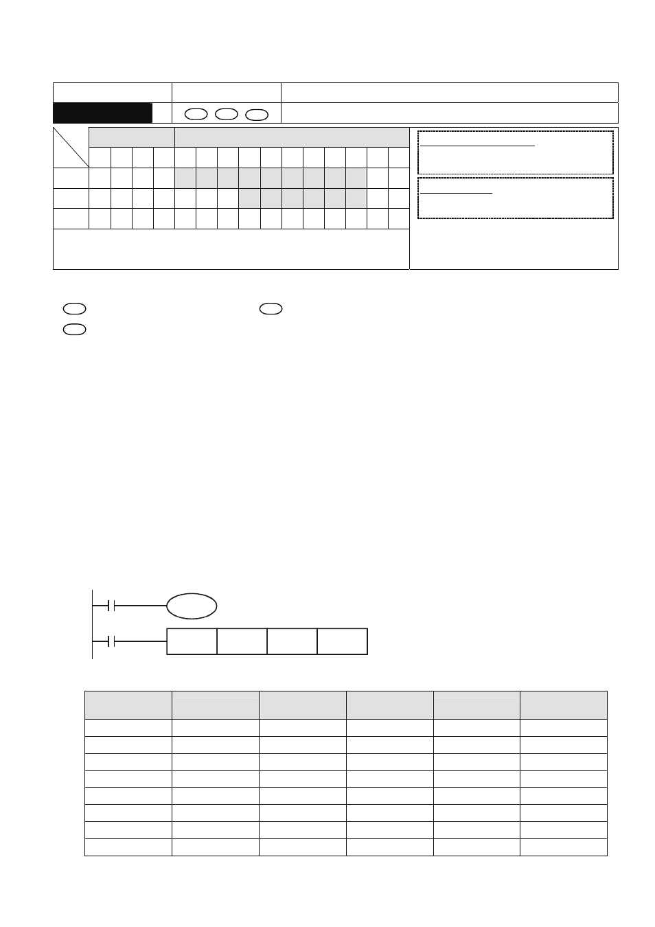
Mnemonic
Operands Function
HEX
S
D
n
Convert ASCII to Hex
Bit Devices
Word Devices
X Y M S K H
KnX
KnY
KnM KnS
T
C
D
E
F
S
D
n
y
Note:
1. Range of n: 1 ~ 256
16-bit instruction (7 Steps)
HEX
Continuous
execution
32-bit instruction
- -
- -
y
Flags: M1161 (8/16 bit mode switch)
Operands:
S
: Start device for source data
D
: Start device for storing the converted result
n
: Number of bits to be converted
Explanations:
1. 16-bit conversion mode: When M1161 = Off, the instruction is in 16-bit conversion mode. ASCII
codes of the 8 high bits and 8 low bits of the hex data in S are converted into hex value and sent to
D
(every 4 bits as a group). n = the number of bits converted into ASCII codes.
2. 8-bit conversion mode: When M1161 = On, the instruction is in 8-bit conversion mode. Every bit of
the hex data in S are converted into ASCII codes and sent to the 8 low bits of D. n = the number of
converted bits. (All 8 high bits of D = 0)
Program Example 1:
1. M1161 = Off: The 16-bit conversion mode
2. When X0 = On, convert the ASCII codes stored in the registers starting from D20 into hex value
and send the result (every 4 bits as a group) to registers starting from D10. n = 4.
X0
HEX
D20
D10
K4
M1001
M1161
3. Assume
S
ASCII code
Converted to
hex
S
ASCII code
Converted to
hex
D20 low byte
H 43
“C”
D24 low byte
H 34
“4”
D20 high byte
H 44
“D”
D24 high byte
H 35
“5”
D21 low byte
H 45
“E”
D25 low byte
H 36
“6”
D21 high byte
H 46
“F”
D25 high byte
H 37
“7”
D22 low byte
H 38
“8”
D26 low byte
H 30
“0”
D22 high byte
H 39
“9”
D26 high byte
H 31
“1”
D23 low byte
H 41
“A”
D27 low byte
H 32
“2”
D23 high byte
H 42
“B”
D27 high byte
H 33
“3”