Sftr – Delta Electronics Extension Digital I/O Module DOP-EXIO14RAE User Manual
Page 132
Appendix D Use of Application Instructions|DOP-EXIO Series
Revision March, 2008, Doc. Name: 2007PDD23000014
D-51
Mnemonic
Operands Function
SFTR
S
D
n
1
n
2
Bit Shift Right
Bit Devices
Word Devices
X Y M S K H
KnX
KnY
KnM KnS
T
C
D
E
F
S
D
n
1
n
2
y
Note:
1. Range of n
1
: 1~ 1,024
2. Range of n
2
: 1~ n
1
16-bit instruction (9 Steps)
SFTR
Continuous
execution
32-bit instruction
- -
- -
y
Flags: None
Operands:
S
: Start No. of the shifted device
D
: Start No. of the device to be shifted
n
1
: Length of data to be shifted
n
2
: Number of bits to be shifted in 1 shift
Explanations:
This instruction shifts the bit device of n
1
bits (desired length for shifted register) starting from D to the
right for n
2
bits. S is shifted into D for n
2
bits to supplement empty bits.
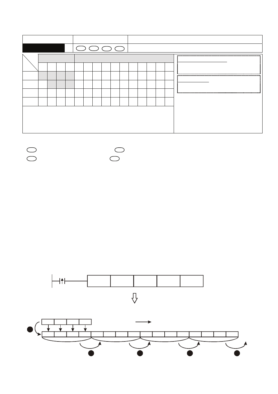
Program Example:
When X0 = Off→On, M0 ~M15 will form 16 bits and shifts to the right (4 bits as a group). The figure
below illustrates the right shift of the bits in one scan.
n
M3 ~ M0 → carry
o
M7 ~ M4 → M3 ~ M0
p
M11 ~ M8 → M7 ~ M4
q
M15 ~ M12 → M11 ~ M8
r
X3 ~ X0 → M15 ~ M12 completed
X0
SFTR
X0
M0
K16
K4
X3
X2
X1
X0
M15 M14 M13 M12 M11 M10
M9
M8
M7
M6
M5
M4
M3
M2
M1
M0
1
2
3
4
5
carry
4 bits as a group shifting to the right