Delta Electronics Extension Digital I/O Module DOP-EXIO14RAE User Manual
Page 68
Appendix C Use of Basic Instructions|DOP-EXIO Series
Revision March, 2008, Doc. Name: 2007PDD23000014
C-3
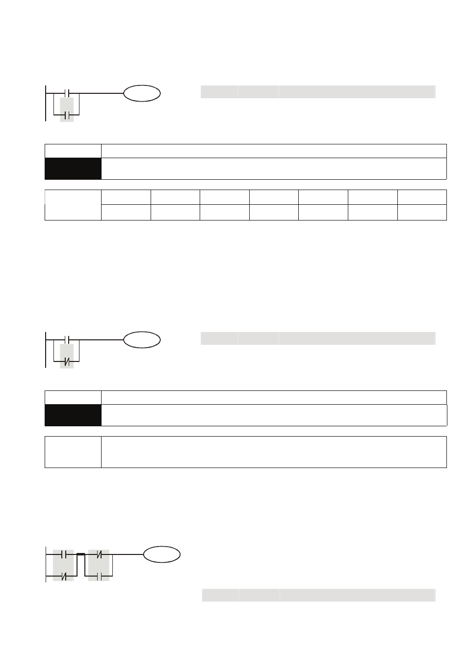
Program Example:
Ladder diagram:
Instruction code:
Operation:
LD
X0
Loading in contact A of X0
OR
X1
Connecting to contact A of X1 in parallel
X0
X1
Y1
OUT
Y1
Driving Y1 coil
Mnemonic Functions
ORI
Parallel Connection- B Contact
X0~X17 Y0~Y17
M0~M1279
S0~S127
T0~T127 C0~C254
D0~D599
Operand
9
9
9
9
9
9
-
Explanation:
The ORI instruction is used in the parallel connection of B contact. The functions are to read out the
status of present designated parallel connection contacts and perform the “ORI” operation with the
logical operation result obtained. The final result will be store in the accumulative register.
Program Example:
Ladder diagram:
Instruction code:
Operation:
LD
X0
Loading in contact A of X0
ORI
X1
Connecting to contact B of X1 in parallel
X0
X1
Y1
OUT
Y1
Driving Y1 coil
Mnemonic Functions
ANB
Series connection- loop blocks
Operand none
Explanation:
To perform the “AND” operation of the preserved logic results and content in the accumulative register.
Program Example:
Ladder diagram:
Instruction code:
Operation:
LD
X0
Loading in contact A of X0
ORI
X2
Connecting to contact B of X2 in parallel
LDI
X1
Loading in contact B of X1
OR
X3
Connecting to contact A of X3 in parallel
ANB
Connecting circuit block in series
X0
X2
Y1
X1
X3
ANB
Block A Block B
OUT Y1
Driving
Y1
coil