Delta Electronics Extension Digital I/O Module DOP-EXIO14RAE User Manual
Page 28
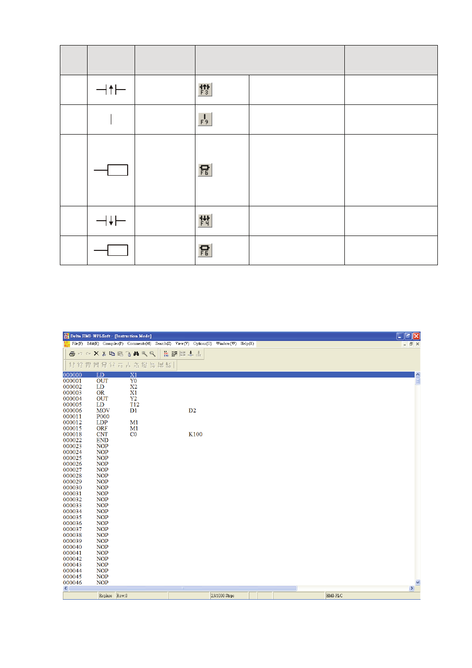
Chapter 3 Creating and Editing Programs|DOP-EXIO Series
Revision March, 2008, Doc. Name: 2007PDD23000014
3-7
Step
Ladder
Symbol
Cursor
Location
Input by clicking the Icon on the
toolbar
Input by using the
Keyboard
10
Row: 4,
Column: 1
Device Name: M
Device Number:1
LDP M1
↵ or + M1 ↵
11
Row: 4,
Column: 2
F9
12
Row: 4,
Column: 2
CNT Instruction
Operand 1: C Device
Number: 0
Operand 2: K Device
Number: 100
CNT C0 K100
↵
13
Row: 5,
Column: 1
Device Name: M
Device Number: 1
LDF M1
↵ or – M1 ↵
14
Row: 6,
Column: 1
END Instruction
END
↵
After the ladder diagram is completed, the user can compile and convert the completed
ladder diagram to instruction codes. The ladder diagram which has been converted to
instruction codes is shown as the figure below.
- 1x9 Bi-Directional Transceiver Module OPBD-155F2J1R (7 pages)
- Single Mode SFP Transceiver LCP-1250B4MDRx (14 pages)
- LC-1250xxxx Series (10 pages)
- Human Machine Interface DOP-AS Series (329 pages)
- Analog Output Module DVP04DA-S (2 pages)
- DeviceNet Slave Communication Module IFD9502 (2 pages)
- LCP-155B4MSRx (12 pages)
- High-Speed PCI 12-Axis Motion Control Card PCI-DMC-B01 (528 pages)
- Network Device DVP01PU-S (2 pages)
- GBIC-1250D5MR (12 pages)
- SPBD-1250A4Q1RT (10 pages)
- SILM4015 (1 page)
- LCP-8500A4EDR (14 pages)
- 10GBASE-SR SFP+ Optical Transceiver LCP-10G3A4EDR (16 pages)
- LCP-155A4HSRx (11 pages)
- LCP-1250RJ3SR-L (9 pages)
- SILM320L (1 page)
- LCP-1250RJ3SR-S (9 pages)
- SIL530 (1 page)
- Extension Digital I/O Module DOP-EXIO28RAE (1 page)
- DVP Series PLC DVP04TC-H2 (2 pages)
- 1x9 Bi-Directional Transceiver Module OPBD-155F1J1R (7 pages)
- Distribution Box TAP-CN01/02/03 (2 pages)
- LCP-200A4HSR (9 pages)
- Pulse Generation Unit DVP01PU-H2 (2 pages)
- Power Connection Interface VFD-PSD01 (1 page)
- Programmable Logic Controller DVP04DA-H2 (2 pages)
- Single Mode SFP Transceiver LCP-1250B4QDRx (13 pages)
- LCP-155B4JSRx Series (12 pages)
- Series Temperature Controller DTD Series (2 pages)
- Brake Modules BUE Series (2 pages)
- PLC DVP Series DVP-SX (2 pages)
- Digital Keypad / Display ASD-PU-01A (1 page)
- Multimode SFP Transceiver LCP-1250A4FDRx (14 pages)
- HMU1362M (1 page)
- RPA-01 (1 page)
- THMR1395 (1 page)
- SFBD-155F2J1RM (7 pages)
- Program Transfer Module DVP-PCC01 (1 page)
- RTU-DNET (41 pages)
- AC Servo Drive ASDA-AB (37 pages)
- Digital Keypad / Display ASD-PU-01B (1 page)
- HMR1045 (1 page)
- CANopen Communication Module DVPCOPM-SL (2 pages)
- SPBD-1250B4Q1R (10 pages)