Zrst – Delta Electronics Extension Digital I/O Module DOP-EXIO14RAE User Manual
Page 134
Appendix D Use of Application Instructions|DOP-EXIO Series
Revision March, 2008, Doc. Name: 2007PDD23000014
D-53
Mnemonic
Operands Function
ZRST
D
1
D
2
Zero Reset
Bit Devices
Word Devices
X Y M S K H
KnX
KnY
KnM KnS
T
C
D
E
F
D
1
D
2
y
Note:
1. Number of operand D1 ≤ Number of operand D2.
2. D
1
and D
2
have to designate devices of the same type.
16-bit instruction (5 Steps)
ZRST
Continuous
execution
32-bit instruction
- -
- -
y
Flags: None
Operands:
D
1
: Start device of the range to be reset
D
2
: End device of the range to be reset
Explanations:
1. When the instruction is executed, area from D
1
to D
2
will be cleared.
2. 16-bit counter and 32-bit counter cannot use ZRST instruction together.
3. When
D
1
> D
2
, only operands designated by D
2
will be reset.
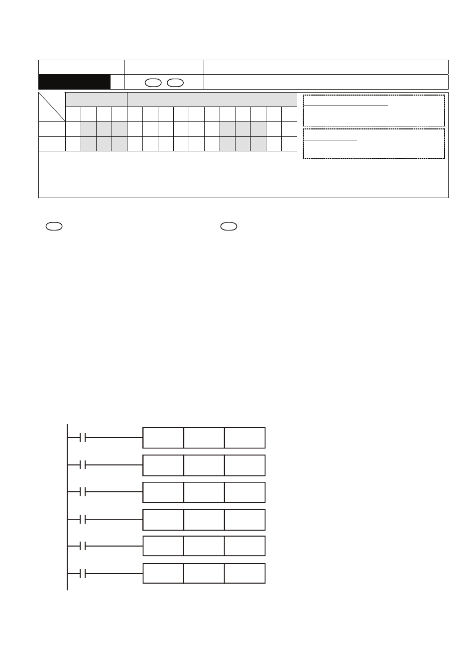
Program Example:
1. When X0 = On, auxiliary relays M300 ~ M399 will be reset to Off.
2. When X1 = On, 16 counters C0 ~ C127 will all be reset (writing in 0; contact and coil being reset
to Off).
3. When X2 = On, steps S0 ~ S127 will be reset to Off.
4. When X3 = On, data registers D0 ~ D100 will be reset to 0.
5. When X4 = On, 32-bit counters C235 ~ C254 will all be reset. (writing in 0; contact and coil being
reset to Off)
ZRST
M300
M399
ZRST
C0
C127
ZRST
T0
T127
ZRST
S0
S127
ZRST
D0
D100
ZRST
C235
C254
X0
X1
X10
X2
X3
X4