Circuit diagram of inputs, Circuit diagram of inputs -54 – QuickLabel 482 Pronto! User Manual
Page 144
8-54
Accessories
•
RXFEH - Reverse line of the signal XFEH
•
RUEL - Reverse line (for all output signals)
•
24P - Operating voltage +24V, Si T 100mA
The printer provides an operating voltage of 24V at PIN15.
Using that voltage a trigger switch or an optical sensor can be connected
to control the peel-off operation without having an external voltage.
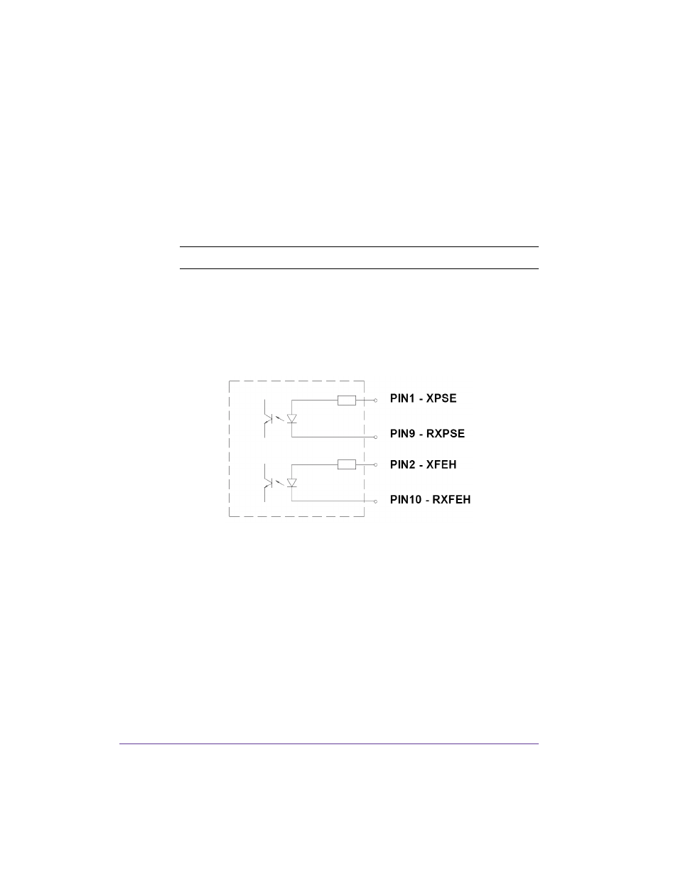
Circuit Diagram of Inputs
The XPSE and XFEH inputs are optocouplers with a current limiting resistor
of 2.2kW giving a voltage of 24V in the input circuit.
For each signal X[IN] there is a separate reverse line X[IN]R via the plug
connector. From that, the following matching pairs of signals result:
The external control device must be equipped with a 15 pin SUB-D connector.
Power supply is given by the peripheral port on the printer.
Caution: DO NOT connect any external voltage at PIN 15!