Grounding, Grounding -6 – Gasboy Atlas Fuel Systems Installation Manual User Manual
Page 68
Reference Information
Wiring
Page 7-6 MDE-4331M Atlas® Fuel Systems Installation Manual · September 2014
Grounding
Following are the grounding requirements for the unit:
• NFPA 70 requires connecting the following to the system ground:
-
Consoles
-
Relay control boxes
-
Pumps and dispensers
-
Circuit breaker panel
-
STPs
-
Electronic leak detectors
• Gasboy requires connecting each pump/dispenser to an equipment-grounding conductor
) located in the conduit, as per NFPA 70, Article 250. Following applies to
the ground conductor:
-
Use a wire that is not smaller than 12 AWG.
-
Use a wire with green or green and yellow striped insulation.
-
Connect to the green grounding screw in the J-box.
-
Ground the providing power under NFPA 70, Article 250.
-
Bond the neutral bus to an approved grounding electrode.
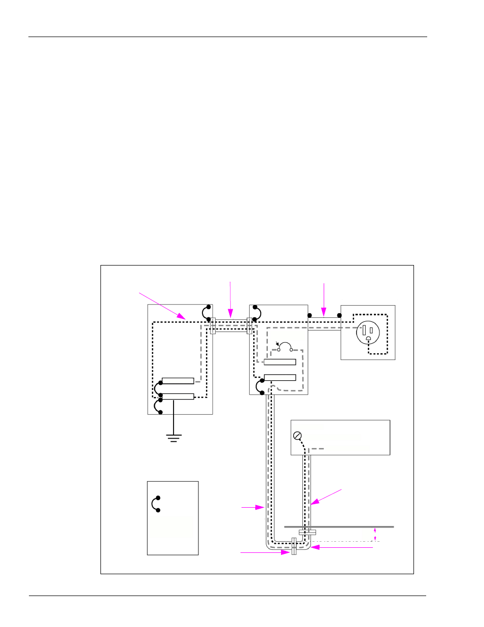
Figure 7-2: Grounding Plan
Main Circuit
Breaker Panel
Pump/dispenser
Circuit Breaker Panel
Gilbarco
Console
Isolated Ground
Power Outlet
(Hubbel IG5261)
Insulated
Grounding
Conductor
Pump/dispenser J-box
Conduit
Metal Conduit
Grounding
Electrode
= Ground
Bond
Notes:
Conduit
Rigid Metal
Conduit
Ground Surface
Rigid Metal
Conduit
Adapter
Refer to NEC
and/or local
codes for
appropriate
conduit
requirements.
Grounding Plan (Typical)
2 Feet
Ground Bus
Neutral Bus
Neutral Bus
Ground Bus
Ground Screw
12AWG Green Ground Wire
White Neutral Wire
Switched Neutral
Circuit Breaker