Se box [lp-70 (see, Figure 17 – Gasboy ATC M05819K00X Kits User Manual
Page 24
Installing the Commercial Atlas (9800K) ATC Kits
Page 24
MDE-4431C Gasboy ATC M05819K00X Kits Installation Manual · February 2013
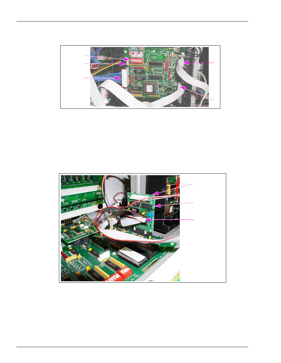
Figure 17: Polycase Box (LP-70) Showing Connections
P2
P5
P6/P7
DIP Switches
P3
21
Locate the Display Adapter harness (W283) provided in the kit (for identification, see
).
22
Connect one Connector on the harness (both are the same) to J4 on the Circuit Board
Assembly [460A4 (see
)] and the other Connector to P6/P7 in the Polycase Box
[LP-70 (see
Figure 18: Circuit Board (460A4) in Place with Connections Made
J1
J4 Display Adapter
Connector (W283)
Circuit Board
Assembly (460A4)
23
Locate the Three-wire Harness (9W172) for IS Barrier provided in the kit.
24
Place the Connector on the harness on P5 in the Polycase Box [LP-70 (see
25
Using three of the crimp splices, connect the wires of the harness to the wires extending from
the top of the IS barrier. Match color codes.
26
Connect the ground wire (the wire with eyelet connector) to the nearest true ground.