Gasboy ATC M05819K00X Kits User Manual
Page 22
Installing the Commercial Atlas (9800K) ATC Kits
Page 22
MDE-4431C Gasboy ATC M05819K00X Kits Installation Manual · February 2013
12
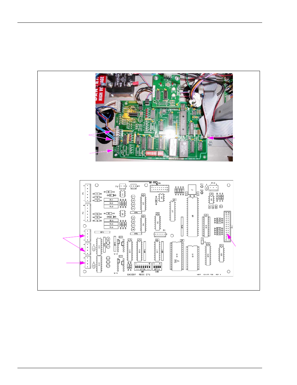
), disconnect the Connector connected to the Pulser 1,
Handles, and Pulser 2 jacks.
Figure 15: CPU PCB Assembly
Pulser 1 and
Handles Jacks
Pulser 2 Jack
LCD Display
Jack
LCD Display
Jack
Pulser 1 and
Handles Jacks
Pulser 2 Jack
(i)
(ii)
CPU PCB Assembly with Connections
CPU PCB Assembly without Connections
13
Locate the Circuit Board Assembly (461A2) provided in the kit (for identification, see
). Connect the assembly to the jacks labeled Pulser 1, Handles, and Pulser 2
at the CPU PCA.
14
Reconnect the Connector removed in step
on
to the Circuit Board Assembly [461A2
(directly above the Pulser 1, Handles, and Pulser 2 Connectors)].
- 216S (18 pages)
- Atlas Fuel Systems Site Prep Manual (42 pages)
- Atlas Technician Programming Quick Ref (2 pages)
- Atlas Fuel Systems Owner Manual (80 pages)
- Gilbarco Global Pumping Unit Operation Manual (42 pages)
- 26 (7 pages)
- Atlas Valve Replacement Kits (10 pages)
- Atlas Fuel Systems Installation Manual (100 pages)
- 9120K (8 pages)
- 9820K (6 pages)
- Atlas Single Std. Inlet Centering Kit (8 pages)
- 8800 Atlas (1 page)
- 9120K Series Service Manual (40 pages)
- 9800A Atlas (6 pages)
- 9800 Atlas (14 pages)
- 9800 Atlas (20 pages)
- M08400 (6 pages)
- 9100 Series (8 pages)
- 9820K Series Installation (62 pages)
- 9853K (8 pages)
- 9216KTW (36 pages)
- Recommended Spare Atlas (14 pages)
- DEF Atlas (28 pages)
- 9820K Series (12 pages)
- 9800Q (1 page)
- Q Series (3 pages)
- 8753E (2 pages)
- 9152AXTW2 (1 page)
- 8800E (2 pages)
- 8800E (1 page)
- 9820Q Series (1 page)
- Atlas Start-up (230 pages)
- 2600A (12 pages)
- 2600A (2 pages)
- 9800Q Front Load Vapor (2 pages)
- 215A (1 page)
- 9800A (4 pages)
- 9820A (1 page)
- 2600A (3 pages)
- 216A (31 pages)
- 215A (2 pages)
- 9800Q Vapor (2 pages)
- Lamp Kit (2 pages)
- 9120Q Pulser (1 page)