Gasboy ATC M05819K00X Kits User Manual
Page 14
Installing the Commercial Atlas (9800K) ATC Kits
Page 14
MDE-4431C Gasboy ATC M05819K00X Kits Installation Manual · February 2013
13
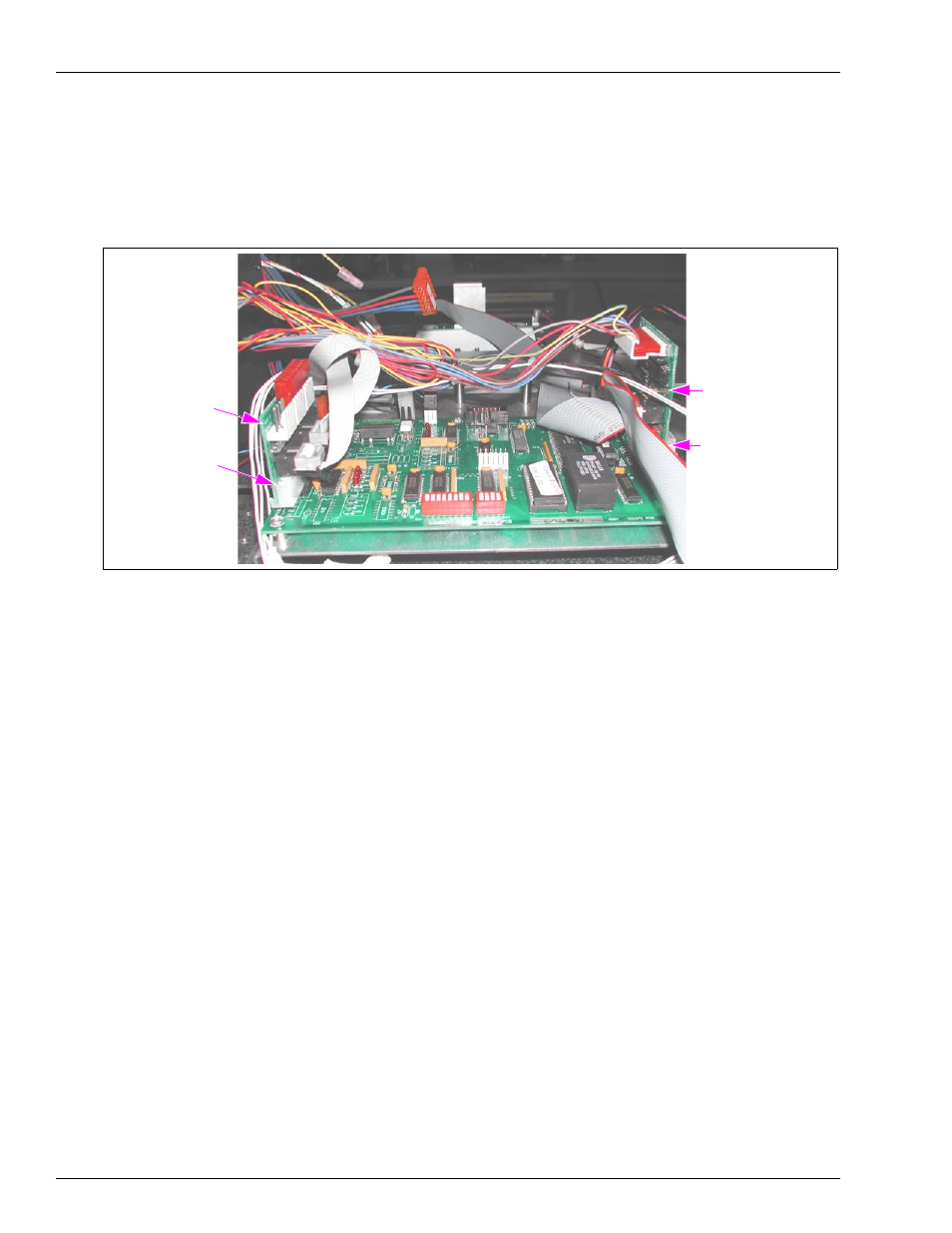
Locate the Circuit Board Assembly (461A2) provided in the kit (for identification,
see
). Connect the assembly to the jacks labeled Pulser 1, Handles, and
Pulser 2 at the CPU Printed Circuit Assembly [PCA (see
)].
Figure 7: CPU with New Connections
Assembly (461A2)
Pulser 1, Handles,
and Pulser 2
Connectors
LCD Display Connector
Assembly (460A4)
14
Reconnect the Connectors disconnected in step
on
to the Circuit Board Assembly
[461A2 (directly above the Pulser 1 and Handles Connectors)].
15
), disconnect the Connector connected to the LCD
Display jack.
16
Locate the Circuit Board Assembly (460A4) provided in the kit (for identification, see
on
). Connect the assembly to the jack labeled LCD Display on the CPU PCA.
17
Reconnect the Connector disconnected in step
to the Circuit Board Assembly (460A4) J1
jack (in center of the board).
18
Locate the Pulser/Handle Ribbon Cable (W284) provided in the kit (for identification, see
on
).