Gasboy ATC M05819K00X Kits User Manual
Page 16
Installing the Commercial Atlas (9800K) ATC Kits
Page 16
MDE-4431C Gasboy ATC M05819K00X Kits Installation Manual · February 2013
21
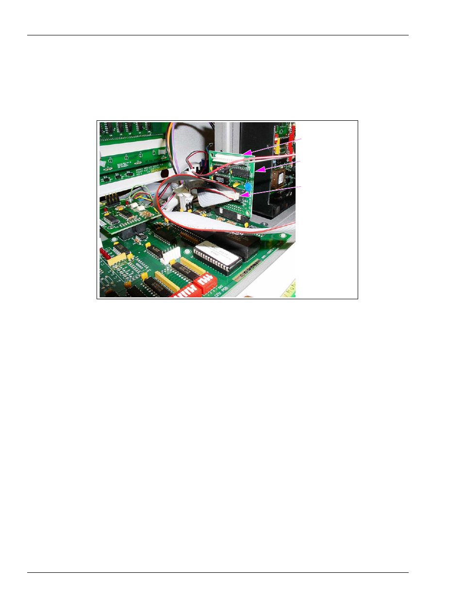
Connect one Connector on the harness (both are the same) to J4 on the Circuit Board
Assembly (460A4) and the other Connector to P6/P7 in the Polycase Box [LP-70 (see
Figure 10: Circuit Board (460A4) in Place with Connections Made
J1
J4 Display Adapter
Connector (W283)
Circuit Board
Assembly (460A4)
22
Locate the Two-wire Harness (W171) for IS barrier provided in the kit.
23
Place the Connector on the harness on P5 in the Polycase Box [LP-70 (see
on
)].
24
Using two of the crimp splices, connect the wires of the harness to the wires extending from
the top of the IS barrier. Match color codes.
25
Cap the end of the green wire from the IS Safety Barrier, using a Cap (0M0205) or an
appropriate size wire nut (these are not part of the kit).
26
Connect the ground wire (the wire with eyelet connector) to the nearest true ground.
27
Disconnect the cable going to P6 Connector of the Pump CPU Board.
28
Connect the cable that was disconnected in step
to P9 Connector in the Polycase Box
(LP-70).
Note: If the user wants to be able to display electronic totals, another Cable (M05119A001)
must be installed and connected to the P6 Connector on the Pump CPU Board.