Important information – Gasboy ATC M05819K00X Kits User Manual
Page 23
MDE-4431C Gasboy ATC M05819K00X Kits Installation Manual · February 2013
Page 23
Installing the Commercial Atlas (9800K) ATC Kits
15
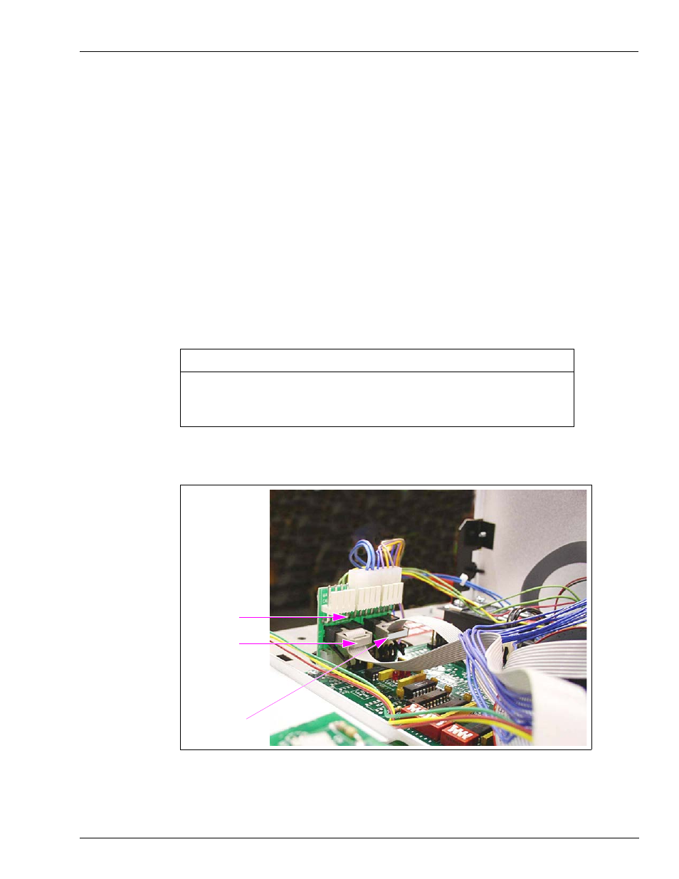
At the CPU PCA (see
), disconnect the Connector connected to the LCD
Display jack.
16
Locate the Circuit Board Assembly (460A4) provided in the kit (for identification, see
on
). Connect the assembly to the jack labeled LCD Display at the CPU PCA.
17
Reconnect the Connector removed in step
on
to the Circuit Board Assembly
(460A4) J1 jack (in center of board).
18
Locate the two Pulser/Handle Ribbon Cables (W284) provided in the kit (for identification,
see
on
).
19
Connect one end of one Cable (W284) to P1 on the Board [461A2 (see
other end to P2 in the Polycase Box [LP-70 (see
)].
20
Connect one end of the second Cable (W284) to P8 on the Board [461A2 (see
the other end to P3 in the Polycase Box [LP-70 (see
)].
Ensure the Cables are connected to the Connectors as follows:
• From P1 of 461A2 to P2 of LP-70 Polycase Box.
• From P8 of 461A2 to P3 of LP-70 Polycase Box.
IMPORTANT INFORMATION
Figure 16: Circuit Board (461A2) with Connections
PCB (461A2)
P1
P8