Appendix, Harge, Rofile – DC Power Technologies Charger Interface Software Manual User Manual
Page 37: Ypes, Iuia, Charge profile types
36
© 2014 Enatel Motive Power Ltd. Specifications subject to change without prior notice. Errors
exempt. Pictures may be representative, actual products may differ.
7. Appendix
7.1. Charge Profile Types
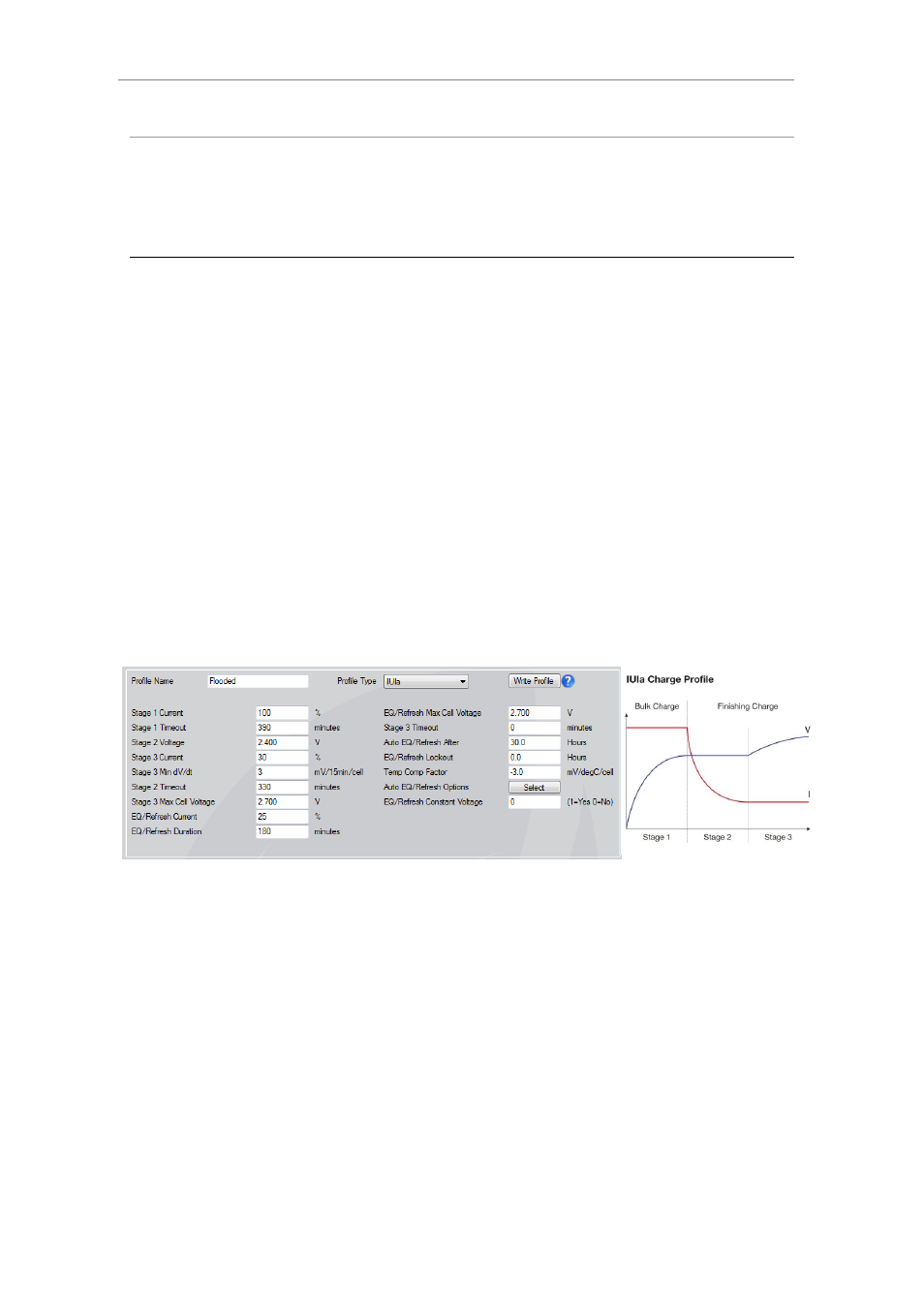
This section describes in detail each stage threshold that defines a charge profile type.
A charge profile type determines the number of stages and the type of current vs. voltage
delivery for that stage.
IUIa
7.1.1.
Most commonly used for charging
flooded traction batteries, the bulk
charge portion of the IUIa is also used
for Opportunity Charging which can be
initiated from the .csv file when
configuring the charger.
The general shape of the IUIa profile is
shown below. The first “I” stage,
constant current, is commonly referred
to as “Bulk Charge”, where the bulk of
the amp hours are returned to the
battery. At the completion of the bulk
stage the amp hours returned will be
approx 80% of the total amp hours
that will be returned by the completion
of the full charge cycle.
The next “U” and “I” stages are
commonly known as the “Finishing
Charge” which provides the required
overcharge to return the battery to its
full capacity and ensure it is ready for
the next discharge cycle, without
excessive temperature rise of the
battery. The “U” part of the finishing
cycle is constant voltage at or near the
voltage when the battery starts
gassing which allows the current to
reduce to a point where it is safe for
the battery to gas freely. The final “I”
stage, again constant current, allows
the battery to gas freely ensuring that
the full capacity is restored.
The termination of the charge is
determined by monitoring the rate of
change of battery voltage over a 15
minute time frame, dV/dt. Different
batteries and different states of charge
perform slightly differently during the
finishing charge and monitoring when
the voltage stops rising is an accepted
way of ensuring an optimal charge has
been achieved.
Stage 1 Current
The percentage of the nominal charger
current (set in the configuration) that
is used for the bulk charge stage,
normally set to 100%.
Stage 1 Timeout
Maximum time the charger will stay in
bulk charge. If this time is exceeded the
charger stops with a major alarm as it
could indicate a faulty battery with short
circuit cells. Whilst the setting is in
minutes the timeout is actually
calculated based on amp hours returned
to the battery rather than just time,
allowing a faulty charger module to
reduce the charge current available and
lengthen the bulk charge time
accordingly.
Although a faulty power module
should always be replaced, in most
situations the charger will still
complete a charge cycle with one
module failed.
Stage 2 Voltage
The setting for the constant voltage
stage, set in accordance with the
battery technology depending on when
a particular battery type starts to gas.
Stage 3 Current
The percentage of the nominal charger
current to which the charge current
needs to reduce to in order to
transition to second constant current
stage. The setting varies with the
capability of the battery technology to
accept current during gassing. This