9 remote addresses – Comtech EF Data MD2401 User Manual
Page 86
MD2401 L-Band Multi Demod Installation and Operation Manual
Rear Panel Interfaces
MN-MD2401
5–6
Revision 7
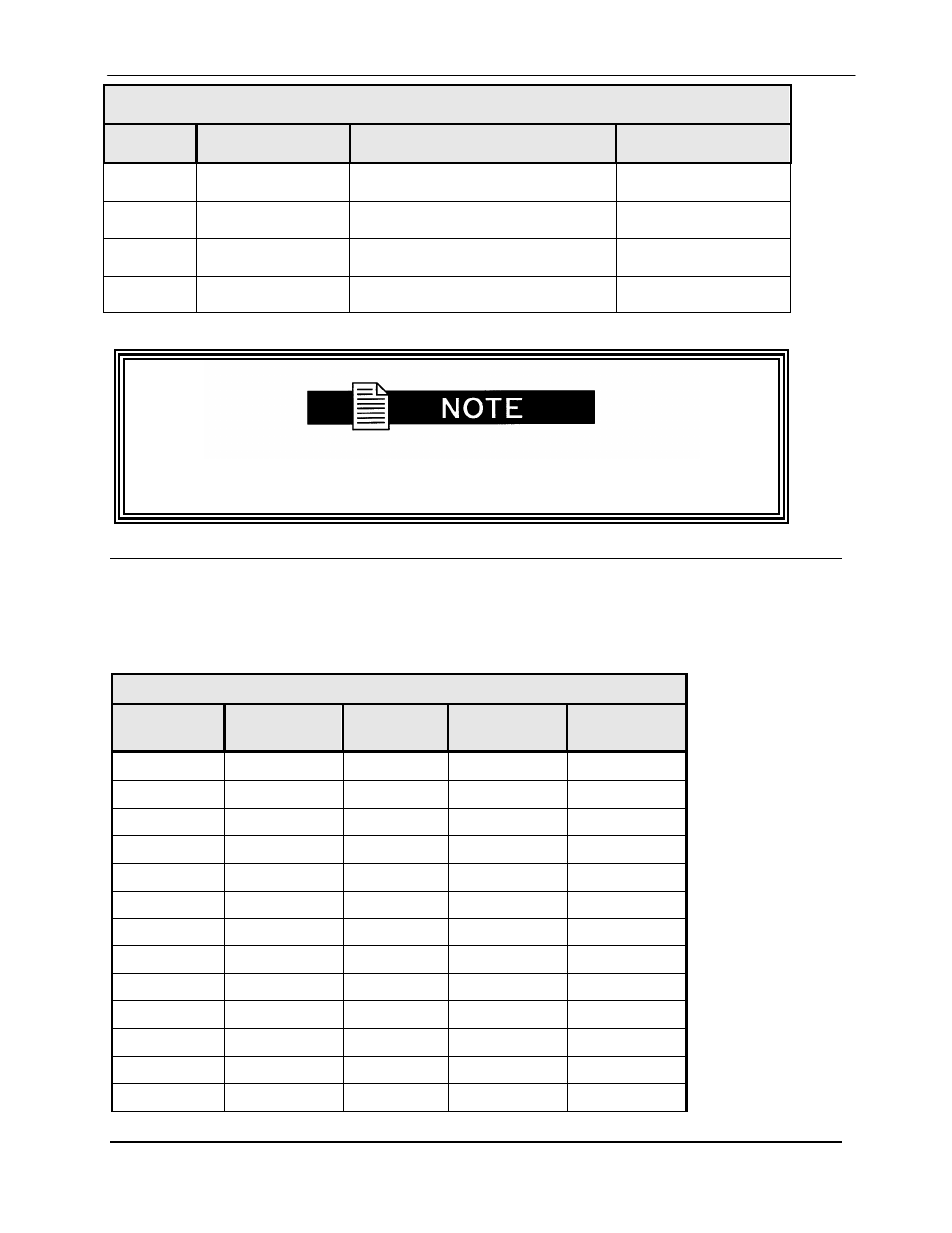
Table 5-3. RS-485 Remote Port – 9-Pin Female D-Sub Connector (J5)
Pin #
Signal
Description
Direction
1
TX-485B
Transmit Data RS-485 (+)
Output
6
TX-485A
Transmit Data RS-485 (-)
Output
8
RX-485B
Receive Data RS-485 (+)
Input
9
RX-485A
Receive Data RS-485 (-)
Input
The user must set demodulator addresses prior to connecting to remote port.
Refer to Section 5.8, “Remote Addresses”.
5.9
Remote Addresses
The demodulator supports up to 16 different remote addresses. Refer to Tables 5-4 and 5-5 for
S1 DIP Switch settings. The S1 DIP switch is located on the Demodulator board (PL/4143).
Refer to Figure 5-3 for the dip switch diagram
Table 5-4. S1 DIP Switch
Position
1
Position
2
Position
3
Position
4
Address in
Decimal
off
off
off
off
32 (default)
on
off
off
off
33
off
on
off
off
34
on
on
off
off
35
off
off
on
off
36
on
off
on
off
37
off
on
on
off
38
on
on
on
off
39
off
off
off
on
40
on
off
off
on
41
off
on
off
on
42
on
on
off
on
43
off
off
on
on
44