2 power – Comtech EF Data MD2401 User Manual
Page 82
MD2401 L-Band Multi Demod Installation and Operation Manual
Rear Panel Interfaces
MN-MD2401
5–2
Revision 7
5.2
Power
The unit is powered from a 100 – 240 VAC, 50 – 60 Hz, 1A source. The switch located on the left
hand side (as viewed from the rear of the unit) turns power on and off to the unit. A chassis
ground connection can be made at the #10-32 threaded stud located to the lower right of the AC
Power Connector.
5.3
Terrestrial Data & Terminal Control Interface (J1)
The J1 Interface supports RS-422 synchrounous Terrestrial Data and RS-232 Remote Terminal
Communications. It is a Female 25-Pin D-Sub Connector. Refer to Table 5-1 for connector
pinouts and Section 4.2 terminal setup and menu descriptions.
Radyne supplies an interfacing Y cables that standardize the terrestrial interface to RS-530 or
RS-449 connection. The Y cable includes a DB 9 connector for Terminal communications that
allows the user to connect to a computer or terminal interface.
• RS530 Y cable is CAR5941
• RS449 Y cable is CA/4263
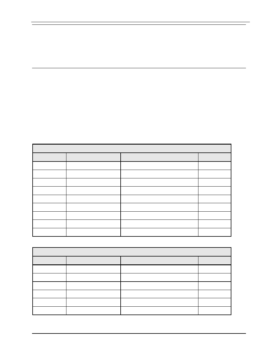
Table 5-1A. Terrestrial Data Interface Port (J1) - 25-Pin ‘D’ Female
Pin No.
Signal Name
Description
Direction
1
Shield
---
3
RXD-A
Receive Data
Output
6
DSR
Data Set Ready (Always True)
Output
7
GND
---
8
CD-A
Demod is Phase Locked
Output
9
RXC-B
Receive Clock
Output
10
CD-B
Demod is Phase Locked
Output
16
RXD-B
Receive Data
Output
17
RXC-A
Receive Clock
Output
Table 5-1B. Terminal Interface Port (J1) - 25-Pin ‘D’ Female
Pin No.
Signal Name
Description
Direction
18
TX-232
RS-232 (Terminal)
Input
20
Unused
---
21
RX-232
RS-232 (Terminal)
Output
22
Unused
---
23
GND
---
25
Unused
---