7 rx in, 1 l-band (j4), 8 remote port (j5) – Comtech EF Data MD2401 User Manual
Page 85
MD2401 L-Band Multi Demod Installation and Operation Manual
Rear Panel Interfaces
MN-MD2401
5–5
Revision 7
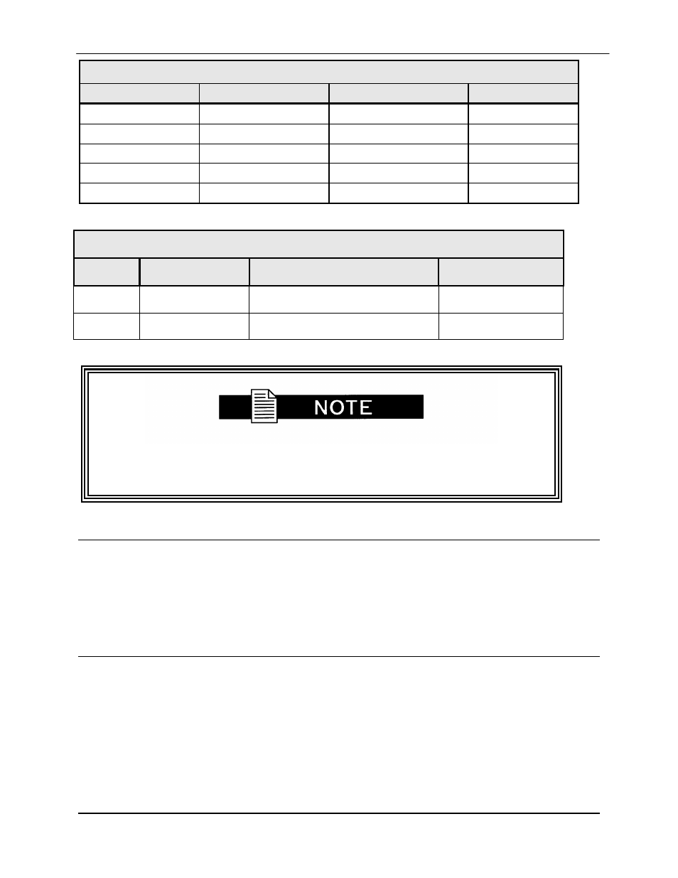
Table 5-2A. Serial Control Interface Port (J3) - 25-Pin ‘D’ Female
Pin No.
RS-232 Signal Name
RS-485 Signal Name
Direction
9
TXD
TXD-B
Output
10
TXD-A
Output
16
RXD
RXD-B
Input
3
RXD-A
Input
7
GND
GND
---
Table 5-2B. AGC Monitor (J3) - 25-Pin ‘D’ Female
Pin #
Signal
Description
Direction
5
AGC
AGC Out
Output
7
GND
Ground
---
J3 Remote Control Interface allows user to directly access each demodulator
individually. J5 is the primary mode of serial remote control. Do not use J3 and
J5 simultaneously.
5.7
RX IN
5.7.1 L-Band (J4)
The Receive Input (J4) is the 950 – 1750 MHz Demodulator IF Input. It is a SMA (1) Connector.
5.8
Remote Port (J5)
The Remote Port (J5) is an RS-485 interface a single port used for remote monitor and control of
all demodulators. It is a female 9-pin D-Sub connector. Refer to Table 5-3 for connector pinouts.
- CDD-880 (124 pages)
- CDM-800 (130 pages)
- ODMR-840 (184 pages)
- CDM-750 (302 pages)
- CDM-840 (244 pages)
- SLM-5650A (420 pages)
- CTOG-250 (236 pages)
- CDM-700 (256 pages)
- CDM-760 (416 pages)
- CDM-710G (246 pages)
- CDM-600/600L (278 pages)
- CDMR-570L (512 pages)
- CDM-625 (684 pages)
- CDM-625A (756 pages)
- CDD-564A (240 pages)
- CDD-564L (254 pages)
- CLO-10 (134 pages)
- MCED-100 (96 pages)
- CDMR-570AL (618 pages)
- CDM-600 LDPC (2 pages)
- BUC Power Supply Ground Cable (2 pages)
- MPP70 Hardware Kit for CDM-570L (4 pages)
- MPP50 Hardware Kit for CDM-570L (4 pages)
- CDM-625 DC-AC Conversion (4 pages)
- CDM-625 DC-AC Conversion with IP Packet Processor (4 pages)
- DMDVR20 LBST Rev 1.1 (117 pages)
- DMD2050E (212 pages)
- DMD-2050 (342 pages)
- DMD1050 (188 pages)
- OM20 (220 pages)
- QAM256 (87 pages)
- DD240XR Rev Е (121 pages)
- MM200 ASI Field (5 pages)
- DM240-DVB (196 pages)
- MM200 (192 pages)
- CRS-150 (78 pages)
- CRS-280L (64 pages)
- CRS-170A (172 pages)
- CRS-180 (136 pages)
- SMS-301 (124 pages)
- CiM-25/8000 (186 pages)
- CiM-25 (26 pages)
- CRS-500 (218 pages)
- CRS-311 (196 pages)
- CIC-20 LVDS to HSSI (26 pages)