5 remote port user interface (j5), 1 protocol structure, 2 protocol wrapper – Comtech EF Data MD2401 User Manual
Page 42
MD2401 L-Band Multi Demod Installation and Operation Manual
User Interfaces
MN-MD2401
4–10
Revision 7
4.5
Remote Port User Interface (J5)
The Remote Port of the MD2401 allows for complete control and monitor functions via an RS-485
or RS-232. An internalDip Switch allows the user to configurable the serial interface.
Control and status messages are conveyed between the MD2401 and the subsidiary modems
and the host computer using packetized message blocks in accordance with a proprietary
communications specification. This communication is handled by the Radyne Link Level Protocol
(RLLP), which serves as a protocol ‘wrapper’ for the M&C data.
Complete information on monitor and control software is contained in the following sections.
4.5.1 Protocol Structure
The Communications Specification (COMMSPEC) defines the interaction of computer resident
Monitor and Control software used in satellite earth station equipment such as Modems,
Redundancy Switches, Multiplexers, and other ancillary support gear. Communication is bi-
directional, and is normally established on one or more full-duplex 9600-baud multi-drop control
buses that conform to EIA Standard RS-485. If a single device is placed on a single control bus,
then the control bus may conform to EIA Standard RS-232.
Each piece of earth station equipment on a control bus has a unique physical address, which is
assigned during station setup/configuration or prior to shipment. Valid decimal addresses on one
control bus range from 32 to 47 for a total of up to 16 devices per bus. Refer to section 5 for
configuring remote port addresses.
4.5.2 Protocol Wrapper
The Radyne COMMSPEC is byte-oriented, with the Least Significant Bit (LSB) issued first. Each
data byte is conveyed as mark/space information with one mark comprising the stop data. When
the last byte of data is transmitted, a hold comprises one steady mark (the last stop bit). To begin
or resume data transfer, a space (00h) substitutes this mark. This handling scheme is controlled
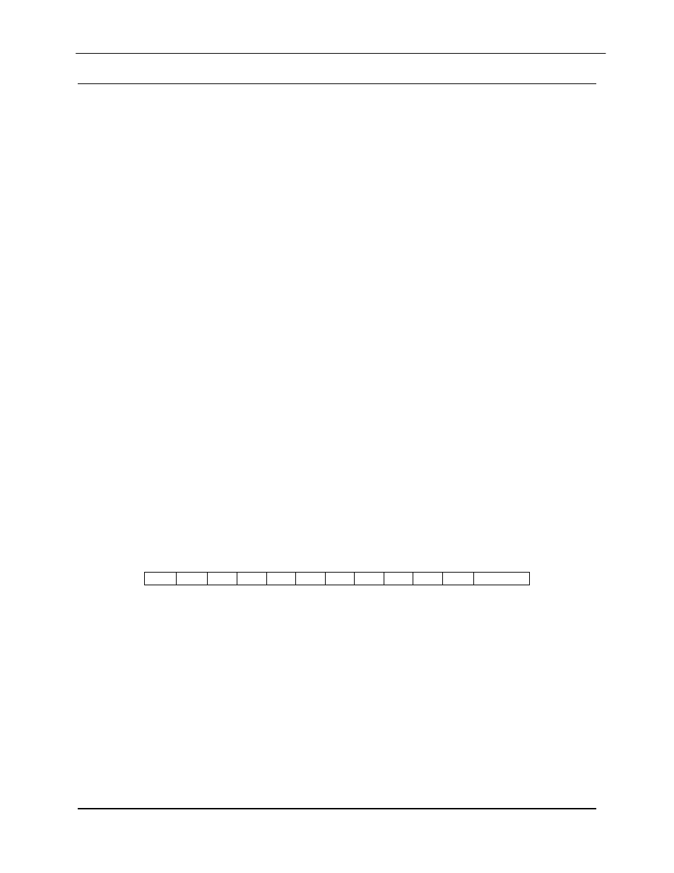
by the hardware and is transparent to the user. A pictorial representation of the data and its
surrounding overhead may be shown as follows:
S1
S2
B
0
B
1
B
2
B
3
B
4
B
5
B
6
B
7
S1
S2, etc.
The stop bit, S1 is a mark. Data flow remains in a hold mode until S1 is replaced by a space. If S1
is followed by a space, the space character is considered a start (ST) and not part of the actual
data (B
0
- B
7
).
The above byte-oriented protocol is standard for UART based serial communication ports such as
Workstation or Personal Computer (PC) COM ports. COM ports should be configured for 8 data
bits, no parity, and one stop bit. For example, for 9600-baud operation, COM ports should be
configured as:
Baud Rate:
9600
Data Bits:
8
Parity:
No Parity (Fixed)
Stop Bits:
1 stop bit