1 rx buffer clock options, 1 rx sat clock, 2 sct: serial clock transmit – Comtech EF Data MD2401 User Manual
Page 29: Figure 3-4. clocking and polarity diagram, Rx satellite clock (recovered from satellite), Sct (internal oscillator)
MD2401 L-Band Multi Demod Installation and Operation Manual
Theory of Operation
MN-MD2401
3–5
Revision 7
EXT REF
EXTERNAL
INTERNAL
SCT CLK
REF FREQ
SRC
RECEIVE
CLOCK & DATA
RECOVERY
SCT
RX SAT
RT
RD
BUFFER CLK
SRC
DEMODULATION
J19
J10
DATA POLARITY
BUFFER CLK POL
NORMAL
INVERTED
INVERT NONE
INV. BASEBAND
INV. TERR DATA
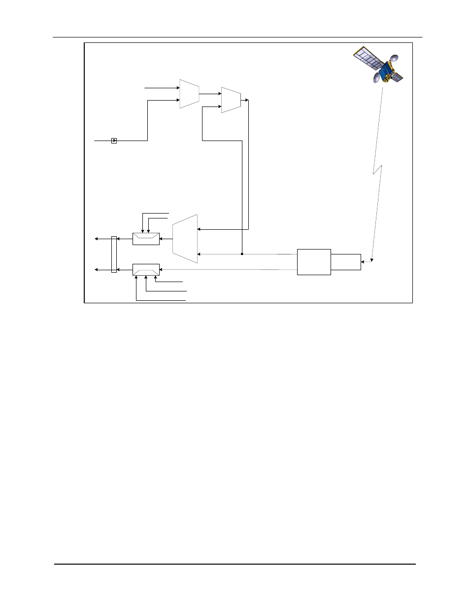
Figure 3-4. Clocking and Polarity Diagram
3.3.1 RX Buffer Clock Options
The modem supports a number of RX Buffer clock options that can be recovered from the
satellite, terrestrial links, internally or externally. The various clocking options allow users to
determine which clock will best fit their applications. Figure 3-7 gives an overview on how the
modem processes the various clocks for the Tx Clock and the Rx Buffer Clock. The modem
allows users to select clock polarity and Rx Clocks may be independently locked. The following
RX Buffer clock selections are available:
Rx Satellite Clock (Recovered from Satellite)
SCT (Internal Oscillator)
3.3.1.1
RX SAT Clock
The RX Sat clock is recovered from the satellite that is received from the distant end. If selected
the Buffer Clock is lock to the RX sat clock.
3.3.1.2
SCT: Serial Clock Transmit
If SCT clock is selected as the RX Buffer clock source, then it should be configured for internal.
SCT is sometimes referred to as Internal Timing or Send Timing (ST).