BayTech MRP units 2012 User Manual
Page 67
Page
67
APPENDIX: LED DISPLAY DESCRIPTION
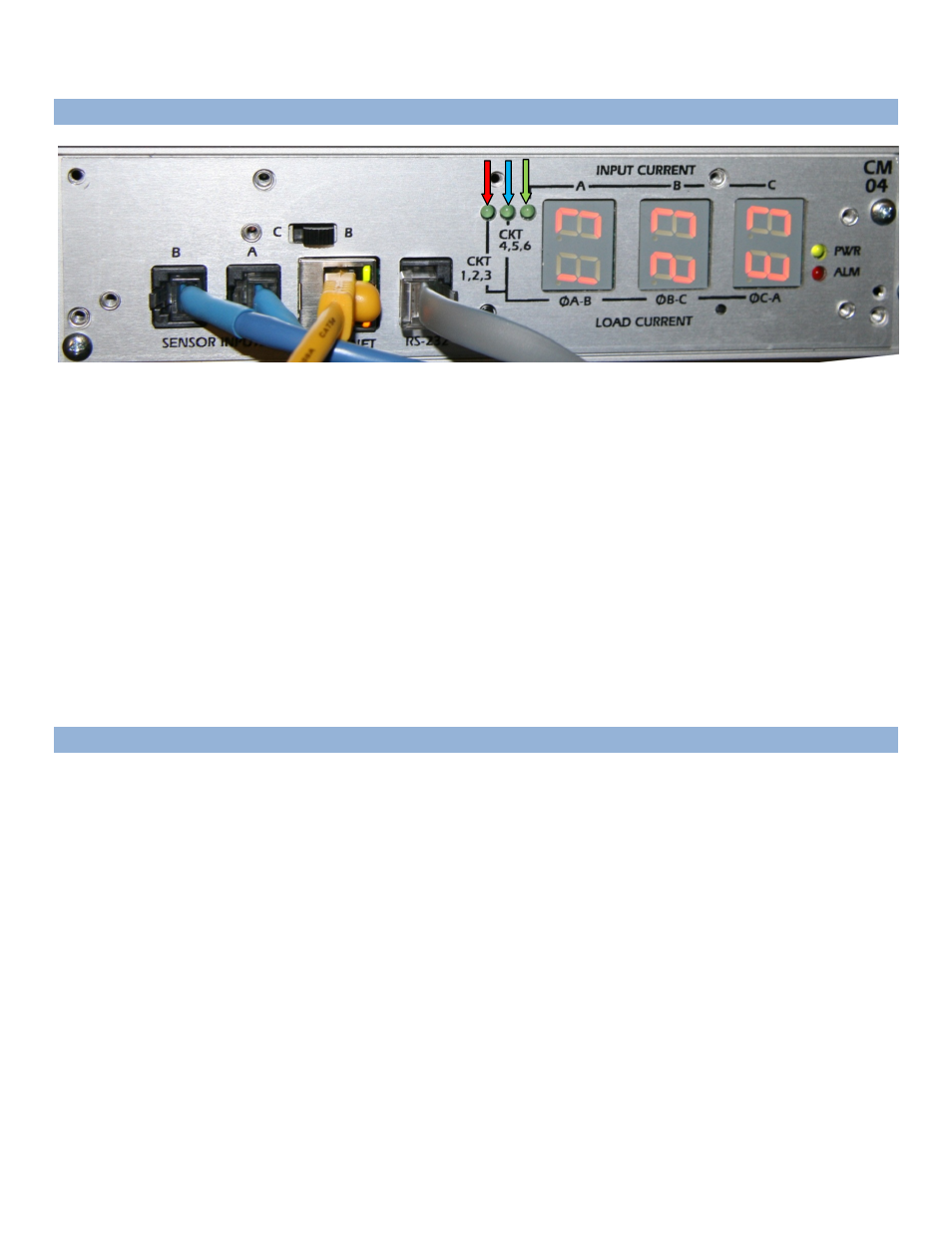
Basic (3) LED display controller, CM03 and CM04 will display the current.
The number of circuit breakers and outlet phase connections will determine the artwork on the module to
identify what the readings are measuring.
The above picture displays the following:
When the first LED,
RED
arrow, is lit, the (3) LEDs display the load current for breakers 1, 2, & 3.
When the second LED,
BLUE
arrow, is lit, the (3) LEDs display the load current for breakers 4, 5, & 6.
When the third LED,
GREEN
arrow, is lit, the (3) LEDs display the total current of each input phase.
The Power LED,
PURPLE
arrow, is lighted when power is applied to unit.
The Current Alarm LED,
ORANGE
arrow, lights when the current exceeds the breaker set threshold. Default is
12 amps.
CM03 = RS232 serial port only
CM04 = RS232 serial port and Ethernet port
APPENDIX: TROUBLESHOOTING
SCROLLING MENU: This may occur in a Master/Slave setup, due to the Master unit being power-up after
the Slave unit and the 8” data cable connecting the serial ports of the Master and Slave together.
CORRECTIVE ACTION: Type “Ctrl+C” then press ’Enter’ to refresh the menu. The keyboard
“Alt+Break” may also work in some programs. The terminal program may have a break command that may
also stop the scrolling. The three break commands work in MS-Hyper-Terminal, Putty, and Reflections.
SMILEY FACE and HEART Symbols (☻♥): Connecting to the EAI232 serial port, the cursor is jumping
back and forth from the Face to the space to the right of the Heart. If these two symbols are displayed, the
Master unit has the Cascade feature enabled and the Ethernet cable is connected. Some terminal programs
will have the cursor do a line-feed and the program appears not to respond.
CORRECTIVE ACTION: Disconnect the Ethernet cable and wait about 10 seconds for the serial port to
revert back to the normal operations with the menu.