AMETEK MX CTSH User Manual
Page 81
California Instruments
Revision H
81
User Manual
MX Series CTSH Compliance Test System
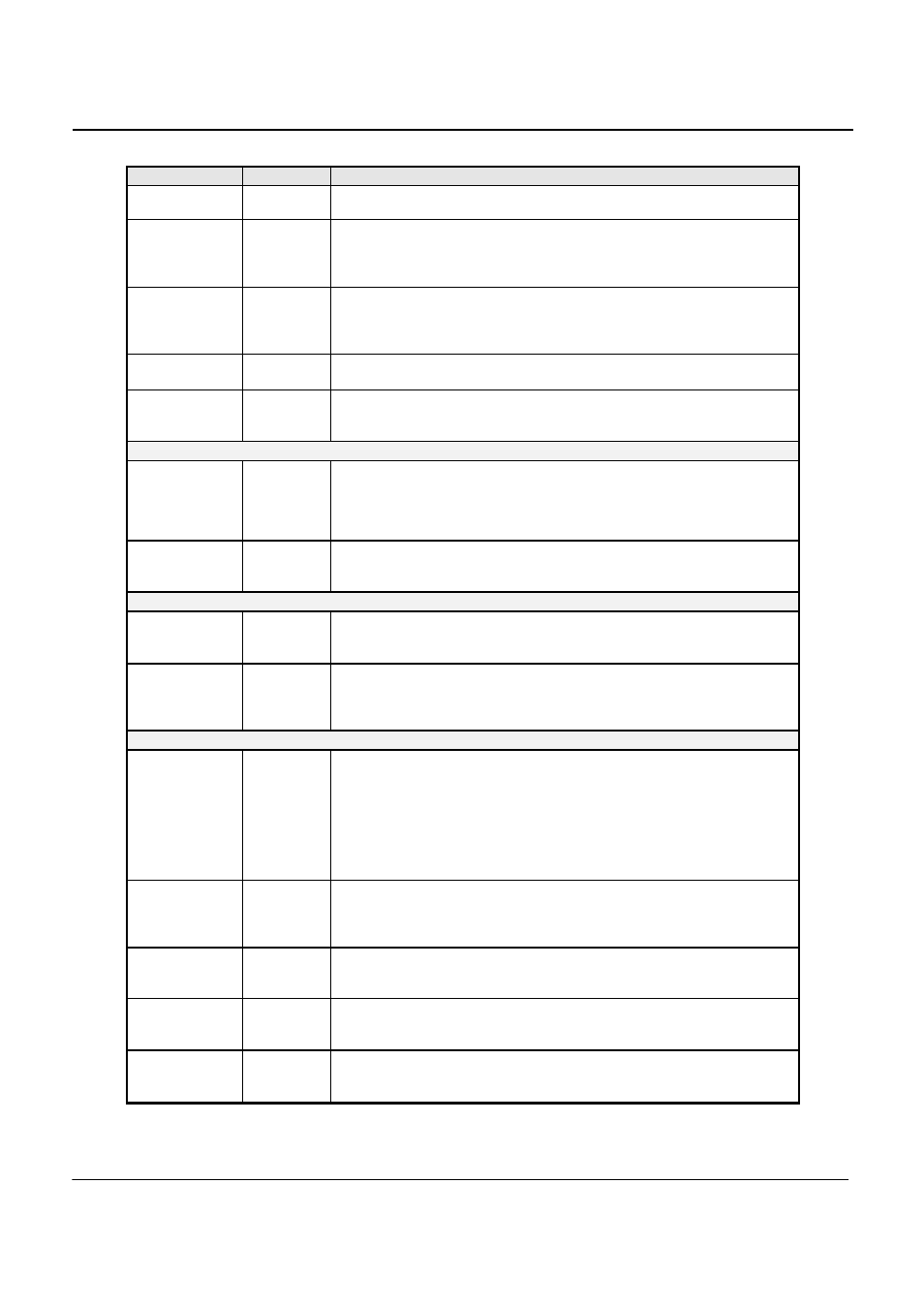
Field / Control
Location
Description
standard requires that d
max
must be less than or equal to 4 % for the EUT
to PASS.
d
c
in %
Center
panel
Displays the present Relative Steady State voltage change (d
c
) in %. This
represents the difference between two adjacent steady-state voltages
relative to the nominal voltage. The standard requires that d
c
must be less
than or equal to 3 % for the EUT to PASS.
Plt # n
Center
panel
Displays the present Long Term Flicker value for Pst period number n. The
Plt period is 120 minutes and is calculated using successive Psti values.
The threshold of irritability for long term flicker is 0.65 and this value is
used as the PASS/FAIL limit.
Instant. Pst
Center
panel
Displays the instantaneous Short Term Flicker value. At the end of each 10
minute period, this value will be the Pst for the period.
Psti #n
Center
panel
Displays the present Short Term Flicker value for period n. The Short Term
Flicker severity is evaluated over a period of 10 minutes. The threshold of
irritability is Pst = 1 and this value is used as the PASS/FAIL limit.
Select Test
Test
selection
This combo box allows one of three test modes to be selected:
•
Test all Flicker parameters
•
Test dc and dt only
•
Test Pst only
Test Margin
Test Margin
This field allows the user to set the test margin from 50 % to 150 %.
Additional information on setting a test margin is shown later in this
chapter.
Graph Display
Graph
panel
The graph panel is used to display either d
c
and d
t
or Ut rms as a function
of time. The user can change display modes using the Graph mode drop
down box located directly above the graph itself.
Graph mode
Display
mode /
Print panel
The Flicker module allows the user to toggle between two display modes.
One mode shows the dc and dt as a function of time. The other mode
shows the Ut rms value as a function of time. Each mode shows a time
windows of about 2 seconds and is updated once every 2 seconds.
Test File
Bottom
panel
This fields shows the currently selected test data file. It also provides a File
button which can be used to change the selected test data file. The test
data file is the file to which new data will be written while a test is running.
Once a test is started, this button in disabled as the test data file cannot be
changed while it is in use by the program. Note that the actual file name
may be too long to fit in the space provided on screen. If this is the case,
use the File button to display the file dialog box which will allow you to see
the entire path and file name.
Test Duration
Bottom
panel
The test duration is the total test time selected by the user. This value can
be set from 0.5 minutes (30 seconds) to 1440 minutes (24 hours). Note
that a Pst and/or All parameter test requires a test time of at least 10
minutes. The default test time is set to 10 minutes.
EUT
Bottom
panel
This field can be used to enter information about the unit under test. The
EUT field contents will be included in the test data file and in any reports
that are printed.
Comments
Bottom
panel
This field can be used to enter any information about the test. The
Comments field contents will be included in the test data file and in any
reports that are printed.
Tested by
Bottom
panel
This field can be used to enter information about the operator. The “Tested
by” field contents will be included in the test data file and in any reports that
are printed.