AMETEK MX CTSH User Manual
Page 113
User Manual
MX Series CTSH Compliance Test System
California Instruments
Revision G
110
C:\Program Files\California Instruments\MXGUI\IEC_Test. The following four EN 61000-4-27 test files are
distributed with the MXGUI program:
File Name
Test Class
Class2.427
2
Class3.427
3
ClassX.427
X
The user may create as many test files as desired using the data entry grid. Changes made can be saved
using the File, Save As… menu entry.
11.5
Waveform Display Tab
This tab displays the three phase output voltage waveforms and their respective phase angles. Each phase
is shown in a different color. This waveform capture is started 10 msec prior to each voltage and phase
change and covers a period of about 100 msec. The last unbalance data display is incorporated in the test
report.
11.6
Operator Observations Tab
This tab may be used to enter any comments concerning the EUT behavior. Any text entered on this page
will become part of the test report. Note that this information is not saved any where other then as part of
the test report.
11.7
Source Regulation
The voltage regulation of the AC Source is always verified. The voltage regulation check verifies AC source
voltage regulation at the beginning of each test under load as called out in the test standard. The voltage
regulation must be less than 2 %. The measured output voltage must be within the source regulation limits
specific in the EN 61000-4-27 standard. If the source regulation check fails, check the system connections.
For higher power loads, make sure the external sense lines are used to sense the voltage at the EUT
terminals.
11.8
Test execution
The selected test mode can be started by pulling down the Run menu and selecting All or by clicking on the
Start button. During test execution, no changes to test parameters are allowed. The test progress can be
monitored at the bottom of the window in the status bar.
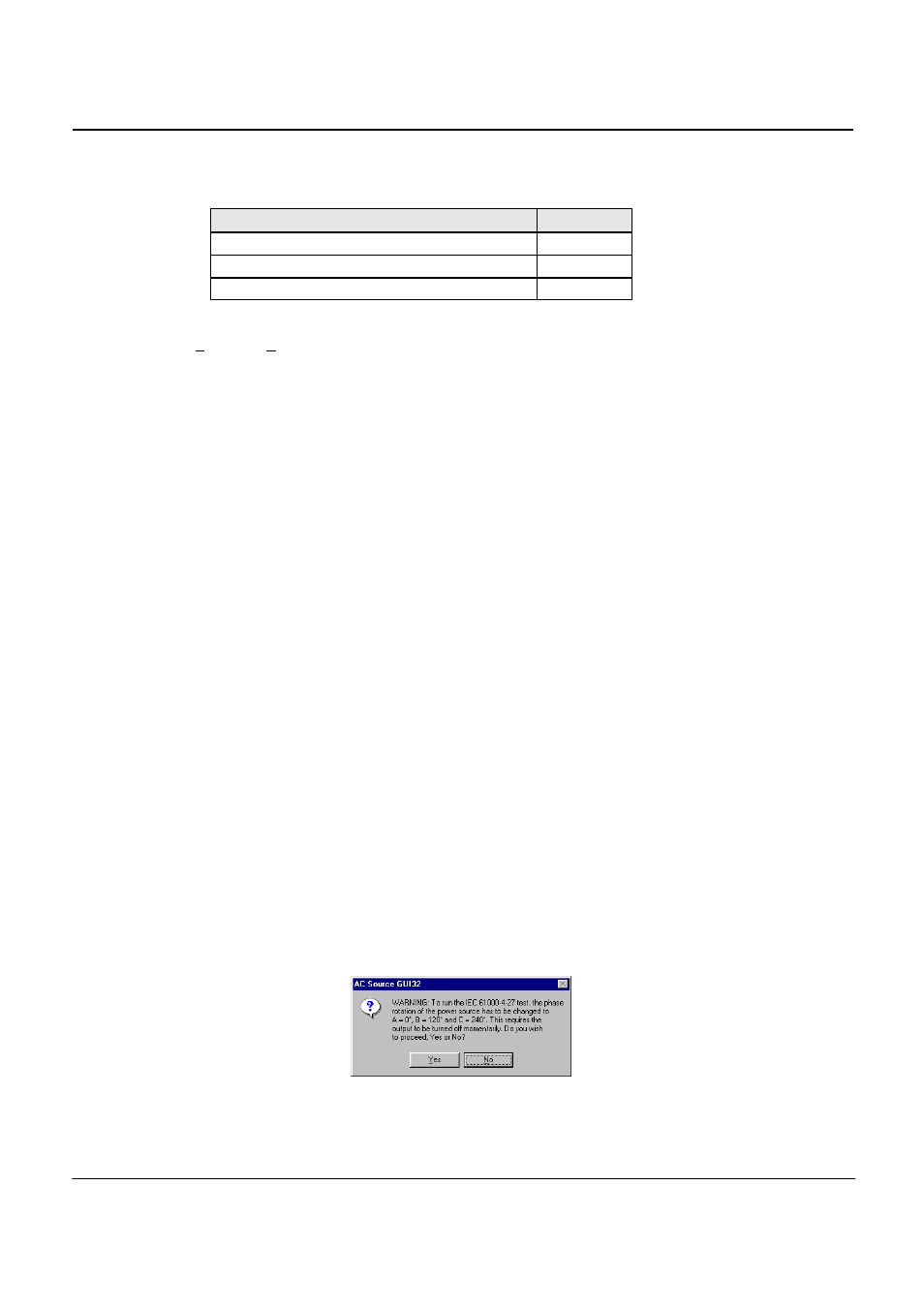
Note that the default phase rotation of the MX Series AC power systems is A = 0, B = 240 and C = 120
(counter clock wise). For the IEC 61000-4-27, the phase rotation must be set to A = 0, B = 120 and C =240.
This is best done with the power to the EUT off. If the test is started and the MX phase rotation is not A = 0,
B = 120 and C =240, a warning will appear prompting the operator to confirm the change in phase rotation.
Selecting No will abort the test with no change to the source output. Selecting Yes will result in the phase
rotation being changed before the test starts. If the phase rotation is already correct, no message appears.