AMETEK MX CTSH User Manual
Page 17
California Instruments
Revision H
17
User Manual
MX Series CTSH Compliance Test System
Stage 2: Connection based on network and equipment data
For equipment not complying with the emission limits for Stage 1 connection, higher emission values are
allowed, provided the short-circuit ratio R
sce
is > 33.
Stage 3: Connection submitted to the local supply authority
If the conditions of neither stage 1 nor stage 2 are fulfilled, the supply authority may accept the connection
of the equipment on the basis of the predicted effects of such a connection being within the local supply
requirements. This has to be negotiated with the local supply utility by the end user of the EUT.
The defined connection stages have different allowable current harmonics limits. The following tables show
the test limits for each connection type.
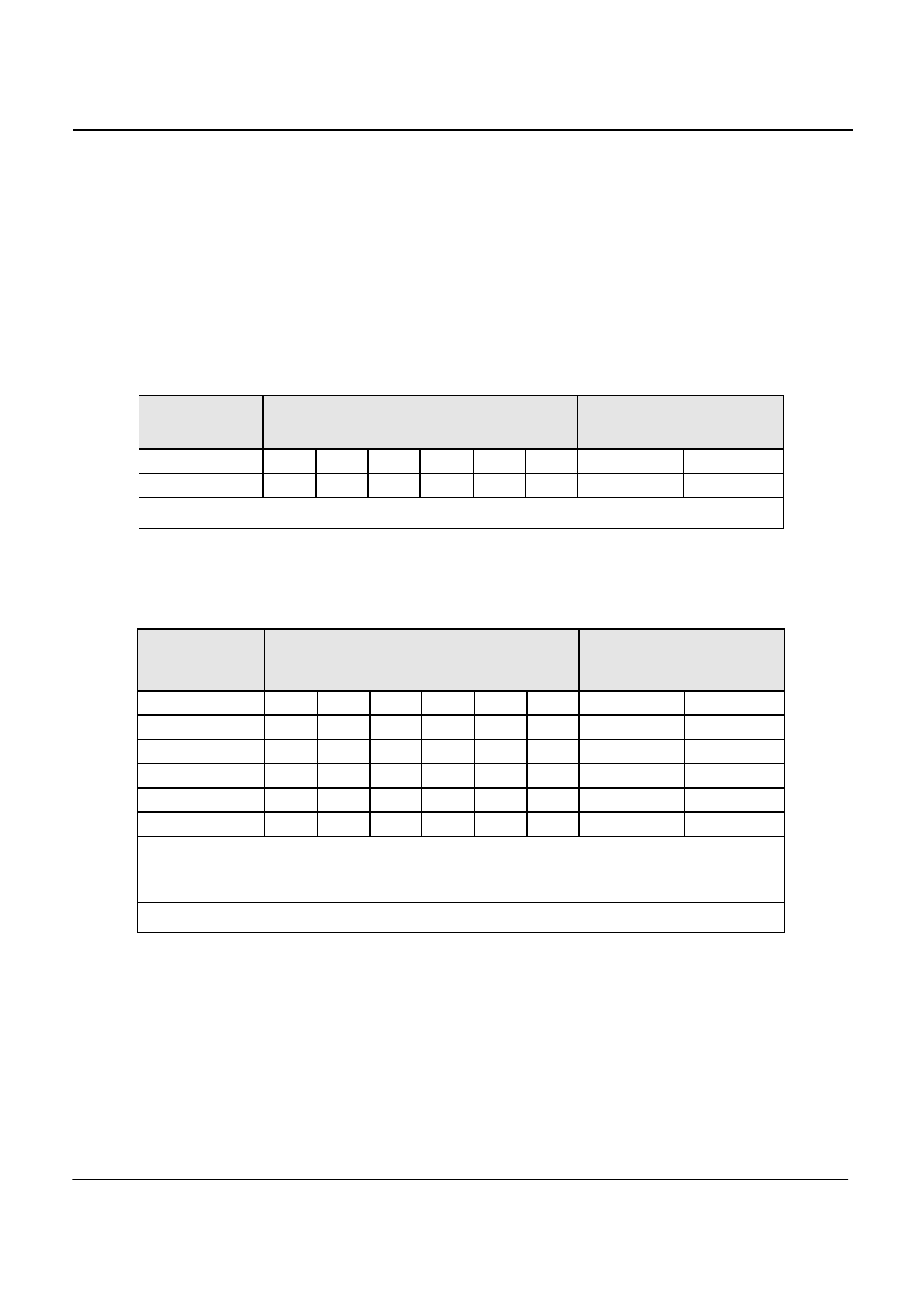
Stage 1:
Minimal R
sce
Admissible individual
harmonic current I
n
/I
1
*
%
Admissible harmonic current
distortion factors
%
I
3
I
5
I
7
I
9
I
11
I
1 3
THD
PWHD
33
21.6
10.7
7.2
3.8
3.1
2
22
23
•
I
1
= rated fundamental current; I
n
= harmonic current component.
Table 2-1: Stage 1 current emission limits for simplified connection of
equipment (values are based on a minimum value of Rsce equal to 33)
Stage 2:
Minimal R
sce
Admissible individual
harmonic current I
n
/I
1
*
%
Admissible harmonic current
distortion factors
%
I
3
I
5
I
7
I
9
I
11
I
13
THD
PWHD
33
21.6
10.7
7.2
3.8
3.1
2
23
23
66
24
13
8
5
4
3
26
26
120
27
15
10
6
5
4
30
30
250
35
20
13
9
8
6
40
40
≥
350
41
24
15
12
10
8
47
47
Note 1 - The relative value of even harmonics shall not exceed 16/n %.
Note 2 - Linear interpolation between successive R
sce
values is permitted.
Note 3 - In the case of unbalanced three-phase equipment, these values apply to each phase.
*
I
1
= rated fundamental current; I
n
= harmonic current component.
Table 2-2: Stage 2 current emission limits for single phase, interphase and
unbalanced three-phase equipment