AMETEK MX CTSH User Manual
Page 54
California Instruments
Revision H
54
User Manual
MX Series CTSH Compliance Test System
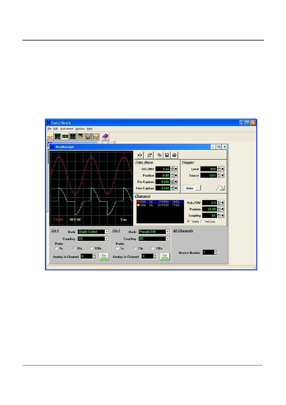
Of course, you may also use the oscilloscope function of the Exacq Bench to display the time domain
signals. Refer to the appropriate section of this manual to identify all the signals and channel numbers, but
for this example, channel 0 is for voltage, and channels 1,2,3 are the (parallel) three current signals. In the
figure below, channel 0 and 3 are displayed (channel 3 is the most sensitive current channel). The CTS
power source was set to 230 Volt – 50 Hz, and a resistive load with a dimmer set to approximately 90
degrees firing angle was applied. The (yellow) current signal was 2.0 Amp rms and the (red) voltage was
230 Volt. The settings for the scope channels and time base function were adjusted to obtain the display as
shown in the figure.
Upon completion of the above tests, you may proceed with installing the CTS software modules that were
supplied with your system.
Figure 3-20: Exacq Scope Test Panel