AMETEK Compact IX 2253 User Manual
Page 98
User Manual
2253i / 2253iX
AMETEK California
Instruments
98
6.5 Non-Routine Output Offset and Gain Calibration
WARNING:
This requires the top cover to be removed and should be done by qualified service
personnel only. Dangerous Voltages are present inside the AC power source.
First adjust amplifier DC offset as follows:
1. Turn on the front panel power circuit breaker.
2. Program the ALC mode to OFF, output mode to DC function, select Low Voltage range and
program 0.0 volts.
3. Use a 100K resistor in series with a 10 uF cap and connect this series network across the
output terminals. Connect an external DVM across the cap. Program the DVM to DC.
4. Close the power source output relay and adjust R97 on the Controller (A4) for zero ±5 mV.
See Figure 6-1 for pot location on the controller board.
5. Remove the series resistor and cap.
6. Repeat for phase B and C. Refer to the table below for the relevant adjustment pots in step 2.
To adjust amplifier output gain, proceed as follows:
1. Connect the DVM directly to the output terminals for phase A.
2. Program AC mode, 0.0 volts AC. Adjust R95 on the controller (A4) for the lowest AC output.
See Figure 6-1 for pot location on the controller board.
3. Select High Vrange, ALC OFF, 240V and 60 Hz. Go to the OUTP CAL screen and adjust the
VOLT FS value for an output of 240 ±1 VAC.
4. Program 240 VAC and 500 Hz. Check the output is 240 ± 5 VAC. If the output is not correct it
indicates an amplifier gain problem.
5. Repeat for phase B and C. Refer to the table below for the relevant adjustment pots in step 2.
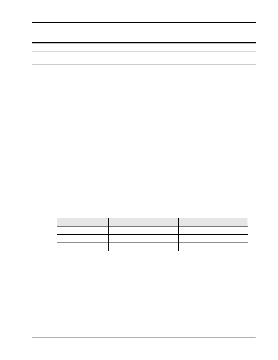
Adjustment
Linearity
DC Offset
Phase A
R95
R97
Phase B
R96
R99
Phase C
R98
R100
Table 6-3: Adjustment pot reference by phase.