AMETEK Compact IX 2253 User Manual
Page 96
User Manual
2253i / 2253iX
AMETEK California
Instruments
96
The shunt must be connected in series with the load. Connect the load to the output. Use a 10
mOhm current shunt of sufficient power rating in series with the load to measure the AC load current.
To calibrate all measurement functions, the desired value for the measurement value of current or
voltage must be entered for the corresponding calibration value. Make the indicated adjustments by
typing in the desired display value. This should be the value indicated by the external DVM. If a 10
milliOhm current shunt is used for current, 100 mV represents 10 amps.
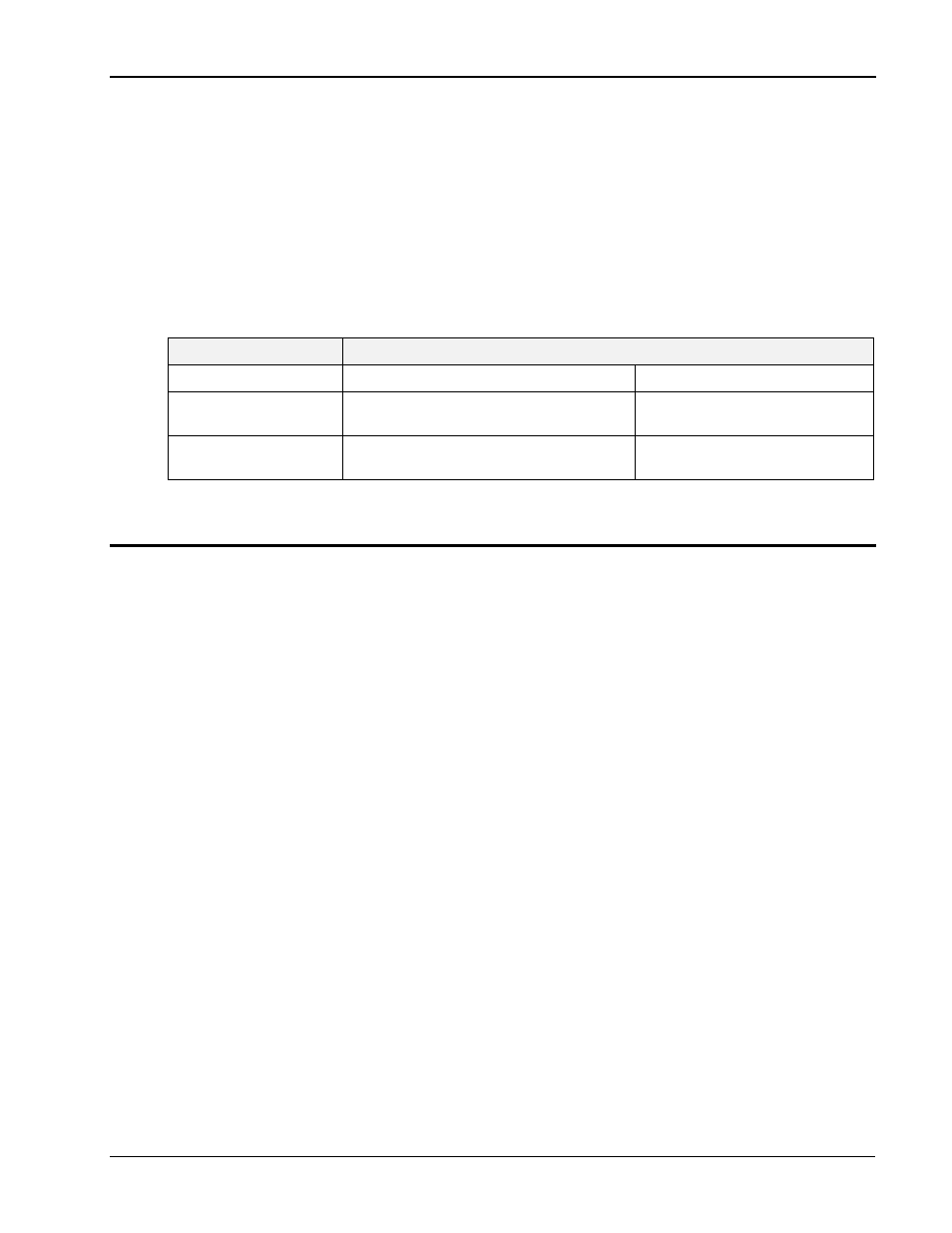
The Calibration Load Table shows required load bank settings for the current measurement calibration
procedure. The current should be calibrated in the lowest voltage range only. (Highest current range).
If only 115VAC input is available, the current can be calibrated using a lower voltage setting (80V) to
get the same 6 A current per phase without drawing more than 500W per phase.
PARAMETER
Model --->
2253i/iX 3 PHS
2253i/iX-MODE 1 PHS
Max current, 115 V, Low
Vrange.
19
700 W
6
2100 W
Max current, 80 V, Low
Vrange (115V AC input)
14
457 W
5
1280 W
Table 6-1: Calibration Load Values
6.3.1 Measurement Cal - AC
AC Volt Full-scale:
Turn OFF the ALC mode from the CONTROL menu first. Select the
phase to be programmed. Program the output voltage to 300 Vrms on
the high voltage range and 400 Hz. Close the output relay. Go to the
MEASUREMENT CALIBRATION screen. Enter the actual AC output
voltage for the MVOLT FS parameter and press the ENTER key.
Note that this calibration process may take up to several minutes to
complete. During this time, the measurement display will be shown.
Once the cal cycle is completed, the LCD display will revert back to
the Calibration screen. To abort the calibration cycle, the BACK key
may be used.
AC Current Full-scale:
Select the phase to be programmed. Calibrate the measurement
current under a constant current condition (OL MODE set to CC) or a
voltage fault may be generated. Apply a load to the output. Program
the output to 115 Vrms on the low voltage range and 400 Hz.
Observe the actual output current and enter this value for the
MCURR FS parameter. Press the ENTER key. Note that this
calibration process may take up to several minutes to complete.
During this time, the measurement display will be shown. Once the
cal cycle is completed, the LCD display will revert back to the
Calibration screen. To abort the calibration cycle, the BACK key may
be used.