AMETEK Compact IX 2253 User Manual
Page 60
User Manual
2253i / 2253iX
AMETEK California
Instruments
60
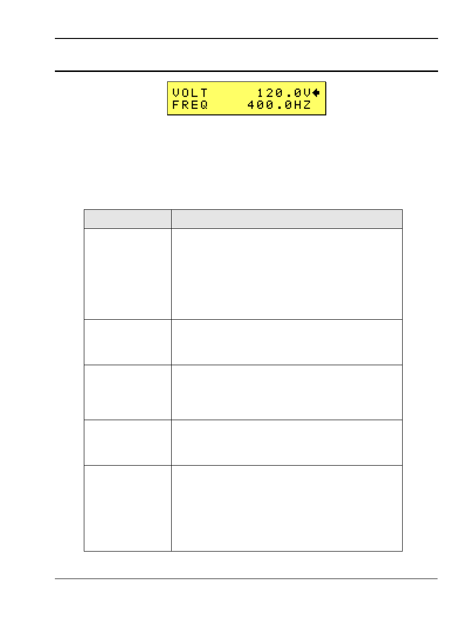
4.2.4 PROGRAM Menu
Figure 4-5: PROGRAM Menu
The PROGRAM menu is shown in Figure 4-5. It can be reached in one of two ways:
1. By selecting the MENU key, selecting the PROGRAM entry and pressing the Enter key.
2. By pressing the SET key.
The PROGRAM menu is used to change primary output parameters. Less frequently used parameters
are located in the CONTROL menu.
The following choices are available in the PROGRAM menus:
ENTRY
DESCRIPTION
VOLTAGE
Programs the output voltage in Vrms. The voltage can be
changed from 0 to its max range value as determined by the
configuration settings and the selected voltage range using the
keypad + Enter or the shuttle (if the voltage field is selected).
NOTE:
Voltage programming is phase specific. To program all
three output phases at the same time, use the PHASE key first
to select coupled mode (A, B, C phase indicator all on). To
program an individual phase only, select the desired phase
using the PHASE key first.
FREQ
Programs the output frequency. The frequency can be changed
from its min to its max value as determined by the configuration
settings using the keypad + Enter or the shuttle (if the frequency
field is selected).
VRANGE
Selects 150V or 300V voltage range (if available). The actual
range values may be different depending on the configuration.
The value of this field can be changed with the shuttle as long
as the active pointer () points to the VRANGE entry. If only
one voltage range is available, this field cannot be changed.
PHASE
Selects the phase angle between the external clock and the
output of the AC source. If the clock source is internal, this
parameter has no effect. This setting always applies to phase A
only, regardless of the phase selection in effect.
FUNC
Selects the waveform for the selected phase. On iX models,
available choices are SINUSOID, SQUARE and CLIPPED or
any user defined waveform that was downloaded to the AC
source waveform memory using one of the available interfaces.
This field is fixed to SINUSOID on ‘i’ models.
NOTE:
Function programming is phase specific. To program all
three output phases at the same time, use the PHASE key first
to select coupled mode (A, B, C phase indicator all on). To
program an individual phase only, select the desired phase