AMETEK Compact IX 2253 User Manual
Page 42
User Manual
2253i / 2253iX
AMETEK California
Instruments
42
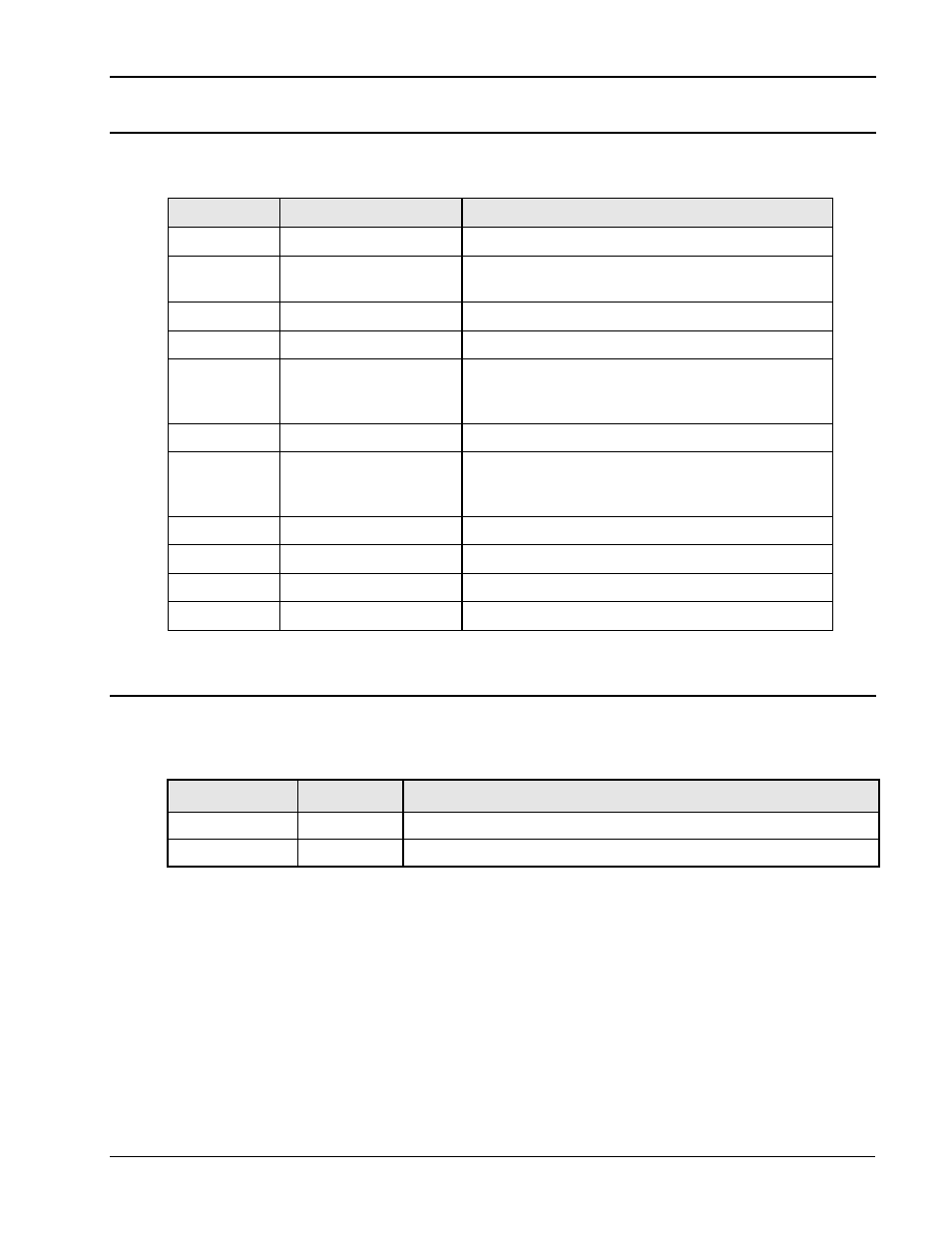
3.7.4 Auxiliary I/O Connector – J18
A high density D style, 15-pin I/O connector is located on the rear panel. Table 3-6 shows connections
by pin number.
Pin
Signal
Description
1 ACOM
Analog
Common
2
RPVA
Remote Programming Voltage all phases (Option -
RPV) or Ext Input phase A (Option –EXT)
3
RPF
Remote Programming Frequency (Option –RPF)
4
/INH
Remote Inhibit. (TTL input)
5
TRIG IN
Trigger Input (TTL input) If external sync option
(–EXS) is installed, this input is reassigned as Ext
Sync.
6
FSTB
Function Strobe or Trigger Output (TTL output)
7
DFI
Discrete Fault Indicator output. Isolated Open
Collector. Can be used to signal external devices
when a fault condition is detected.
8 DCOM
Digital
Common
9
EXTB
External input for phase B (Option -EXT).
10
EXTC
External input for phase C (Option -EXT).
11-15
Reserved
Do not use.
Table 3-6: DB15 Auxiliary I/O Connector
3.7.5 BNC Connectors (-LKM / -LKS options) – J19/J20
BNC connectors. Functions are called out on rear panel decal. Table 3-7 shows connections for the
optional -LKM and -LKS clock and lock mode. This option is available on iX models. Refer to section
3.9 for more details.
BNC
Ref.
Description
CLOCK
J19
Clock Option (TTL output on Master / TTL input on Auxiliary)
LOCK
J20
Lock Option (TTL output on Master / TTL input on Auxiliary)
Table 3-7: BNC Connectors