AMETEK Compact IX 2253 User Manual
Page 104
User Manual
2253i / 2253iX
AMETEK California
Instruments
104
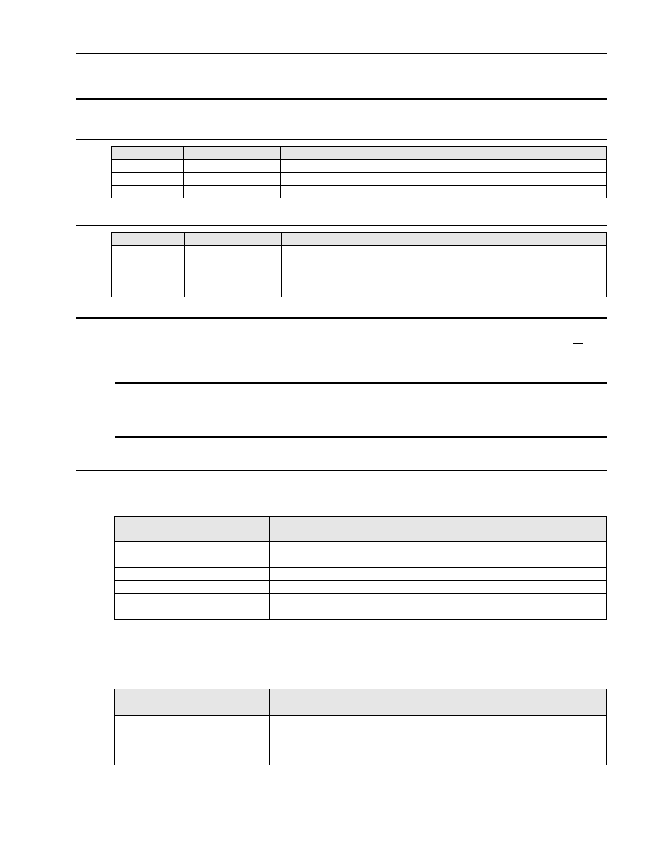
7.6.2 POWER BOARD
7.6.2.1 HIGH VOLTAGE DC INPUT
PINS
NAME
DESCRIPTION
E1
+250V_IN
+250 Vdc @ <5 Adc, must be able to sink current from module
E2
HV_COM_IN
Return for +/- 250V_IN
E3
-250V_IN
-250 Vdc @ <5 Adc, must be able to sink current from module
7.6.2.2 HIGH VOLTAGE OUTPUT
PINS
NAME
DESCRIPTION
E4
HV_COM_OUT
Return for E5 and E6
E5
OUTPUT_LEFT
0 – 150 Vac, 375 VA max from 120 Vac to 150 Vac, 3.13 Arms
max
E6
OUTPUT_RIGHT Same as for E5
7.6.3 CONFIGURATION
The module may be configured to operate as two independent 375 VA LO RANGE half bridges or as
a single 750 VA dual range half/full bridge. Because DIP switches are used to set the operation of
each power module, configuration may only be performed manually.
Note: Unless a module was exchanged in the field, the i/iX comes factory configured for the
correct mode of operation and these dip-switch settings should normally not have to
be changed. This information is provided for reference only.
Only factory authorized personnel should use this information if needed.
7.6.3.1 DIP SWITCH SETTINGS
DIP SWITCH S1
DIP switch S1 selects which oscillator phase will drive each half bridge.
DIP SWITCH
POSITION
NAME
FUNCTION
1
LA
ON for LEFT = Phase A (LB, LC must be OFF)
2
RA
ON for RIGHT = Phase A (RB, RC must be OFF)
3
LB
ON for LEFT = Phase B (LA, LC must be OFF)
4
RB
ON for RIGHT = Phase B (RA, RC must be OFF)
5
LC
ON for LEFT = Phase C (LA, LB must be OFF)
6
RC
ON for RIGHT = Phase C (RA, RB must be OFF)
DIP SWITCH S2 – 2 Positions
For 6005-701-1 control board (Assy rev H or higher) DIP switch S2 configures the source of the error
amplifier drive signal for single or three phase mode.
DIP SWITCH
POSITION
NAME
FUNCTION
1
IL
ON to connect error amplifier signal to the master error amplifier
signal. This switch must be ON for any single module system, or if
the module is a master in a multiple module system. This switch
must be OFF if the LEFT amplifier of the module is auxiliary to a