AMETEK Compact IX 2253 User Manual
Page 44
User Manual
2253i / 2253iX
AMETEK California
Instruments
44
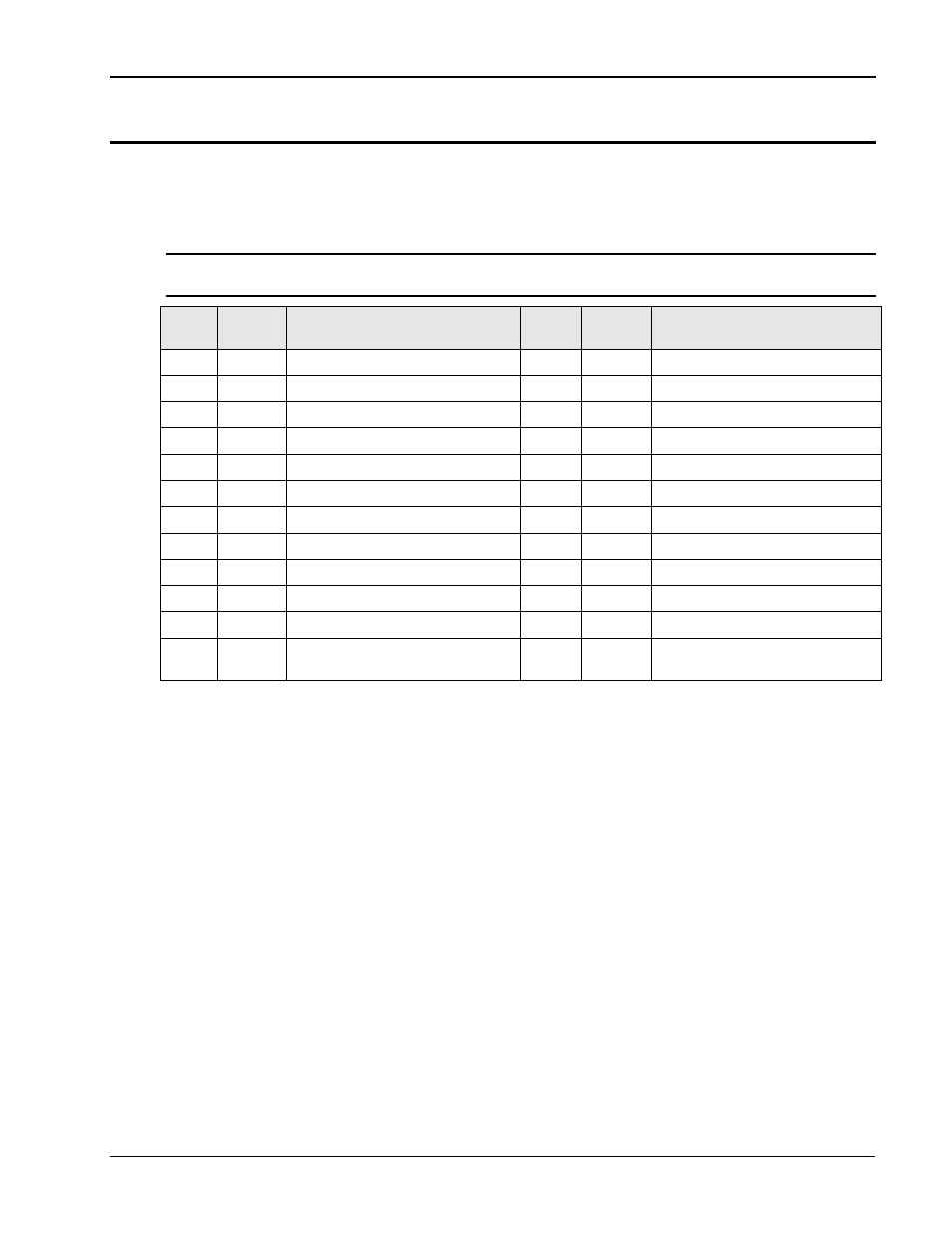
3.7.8 GPIB Interface – J17
A standard IEEE488/ANSI MC1.1; 24 pin GPIB connector is located on the rear panel on al 2253iX
models. Maximum cable length is 20 meters, or 2 meters per device - whichever is less. Maximum
number of devices is 15. Devices may be connected in either a Star or Linear fashion. Jack screws
with Metric threads are black.
Note: On 2253i models, the GPIB interface is optional. If not installed, this connector is not
present.
Pin #
Signal
Names
Signal Description
Pin #
Signal
Names
Signal Description
1
DIO1
Data Input/Output Bit 1
13
DIO5
Data Input/Output Bit 5
2
DIO2
Data Input/Output Bit 2
14
DIO6
Data Input/Output Bit 6
3
DIO3
Data Input/Output Bit 3
15
DIO7
Data Input/Output Bit 7
4
DIO4
Data Input/Output Bit 4
16
DIO8
Data Input/Output Bit 8
5
EOI
End-Or-Identify
17
REN
Remote Enable
6
DAV
Data Valid
18
Shield
Ground (DAV)
7
NRFD
Not Ready For Data
19
Shield
Ground (NRFD)
8
NDAC
Not Data Accepted
20
Shield
Ground (NDAC)
9
IFC
Interface Clear
21
Shield
Ground (IFC)
10
SRQ
Service Request
22
Shield
Ground (SRQ)
11
ATN
Attention
23
Shield
Ground (ATN)
12
Shield
Chassis Ground
24
Single
GND
Signal Ground.
Table 3-10: GPIB Interface Connector pin out.