Compactflash connector (con1) – Altera Stratix II EP2S180 DSP Development Board User Manual
Page 41
Altera Corporation
Core Version a.b.c variable
2–33
Stratix II EP2S180 DSP Development Board Reference Manual
Board Components & Interfaces
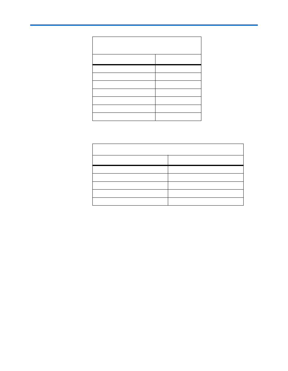
lists the reference information for the Ethernet MAC/PHY.
CompactFlash Connector (CON1)
The CompactFlash connector header (CON1) enables hardware designs
to access a CompactFlash card. The following two access modes are
supported:
■
ATA (hot-swappable mode)
■
IDE (IDE hard-disk mode)
Most pins of CON1 connect to I/O pins on the FPGA. The following pins
have special connections:
■
Pin 13 of CON1 (VCC) is driven by a power MOSFET that is
controlled by an FPGA I/O pin. This allows the FPGA to control
power to the CompactFlash card for the IDE connection mode.
■
Pin 26 of CON1 (CD1#) is pulled up to 5V through a 10-K
Ω resistor.
This signal is used to detect the presence of a CompactFlash card.
When the card is not present, the signal is pulled high through the
pull-up resistor.
SE_D25
AL28
SE_D26
AK28
SE_D27
AK29
SE_D28
AC13
SE_D29
AD10
SE_D30
AC11
SE_D31
AE11
Table 2–27. Ethernet MAC/PHY Reference
Item
Description
Board reference
U16
Part Number
LAN91C111-NE
Device description
Ethernet MAC/PHY
Manufacturer
SMSC
Manufacturer web site
www.smsc.com
Table 2–26. Ethernet MAC/PHY (U16) (Part 3
of 3)
Pin Name
Pin Number