A/d converters – Altera Stratix II EP2S180 DSP Development Board User Manual
Page 24
2–16
Core Version a.b.c variable
Altera Corporation
Stratix II EP2S180 DSP Development Board Reference Manual
Board Components
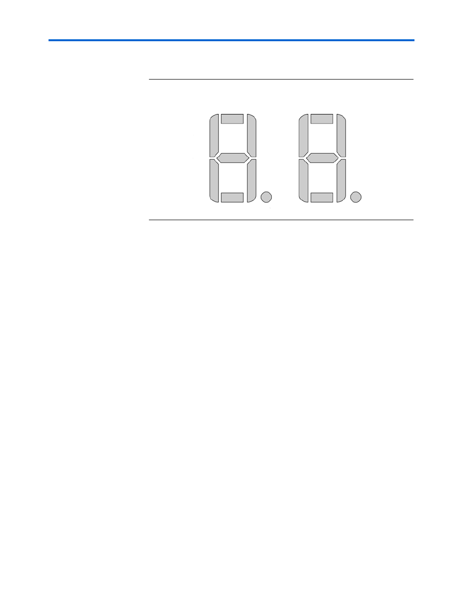
shows the pin-outs for the 7-segment display.
Figure 2–4. Pin-Out Diagram for the Dual 7-Segment Display
A/D Converters
The Stratix II EP2S180 DSP development board has two 12-bit A/D
converters that produce samples at a maximum rate of 125 mega-samples
per second (MSPS). The A/D subsystem of the board has the following
features:
■
The data output format from each A/D converter to the Stratix II
device is in two’s complement format.
■
The circuit has a wideband, AC-coupled, differential input useful for
IF sampling. The analog inputs are transformer-coupled to the A/D
converter to create a balanced input. To maximize performance, two
transformers are used in series. The Analog Devices data sheet for
the AD9433 device describes the detailed operation of this circuit.
■
Any required anti-aliasing filtering can be installed externally. If
needed, users can purchase in-line SMA filters from a variety of
manufacturers, such as Mini-Circuits (www.minicircuits.com).
1
The transformer-coupled AC circuit has a lower 3-dB frequency,
of approximately 1 MHz.
The clock signal that drives the A/D converters can originate from the
Stratix II device, the external clock input, or the on-board 100-MHz
oscillator. Jumper J3 controls which clock is used for ADC A and J4 is used
HEX_0A HEX_1A
HEX_0D HEX_0DP HEX_1D HEX_1DP
HEX_0C
HEX_0B
HEX_0E HEX_0F
HEX_0G
HEX_1G
HEX_1C
HEX_1B
HEX_1E H
E
X
_
1F