Configuration & reset buttons, Sw8 - cpu reset, Sw8 – cpu reset – Altera Nios Development Board Cyclone II Edition User Manual
Page 46
2–34
Reference Manual
Altera Corporation
Nios Development Board Cyclone II Edition
May 2007
Board Components
Configuration & Reset Buttons
The Nios development board uses dedicated switches SW8, SW9 and
SW10 for the following fixed functions:
SW8 – CPU Reset
When SW8 is pressed, a logic-0 is driven onto the FPGA I/O pin C5
(DEV_CLRn). The result of pressing SW8 depends on how the FPGA is
configured. Refer to
The factory-programmed Nios II reference design treats SW8 as a CPU-
reset button. The Nios II reference design resets and starts executing code
from its reset address when SW8 is pressed.
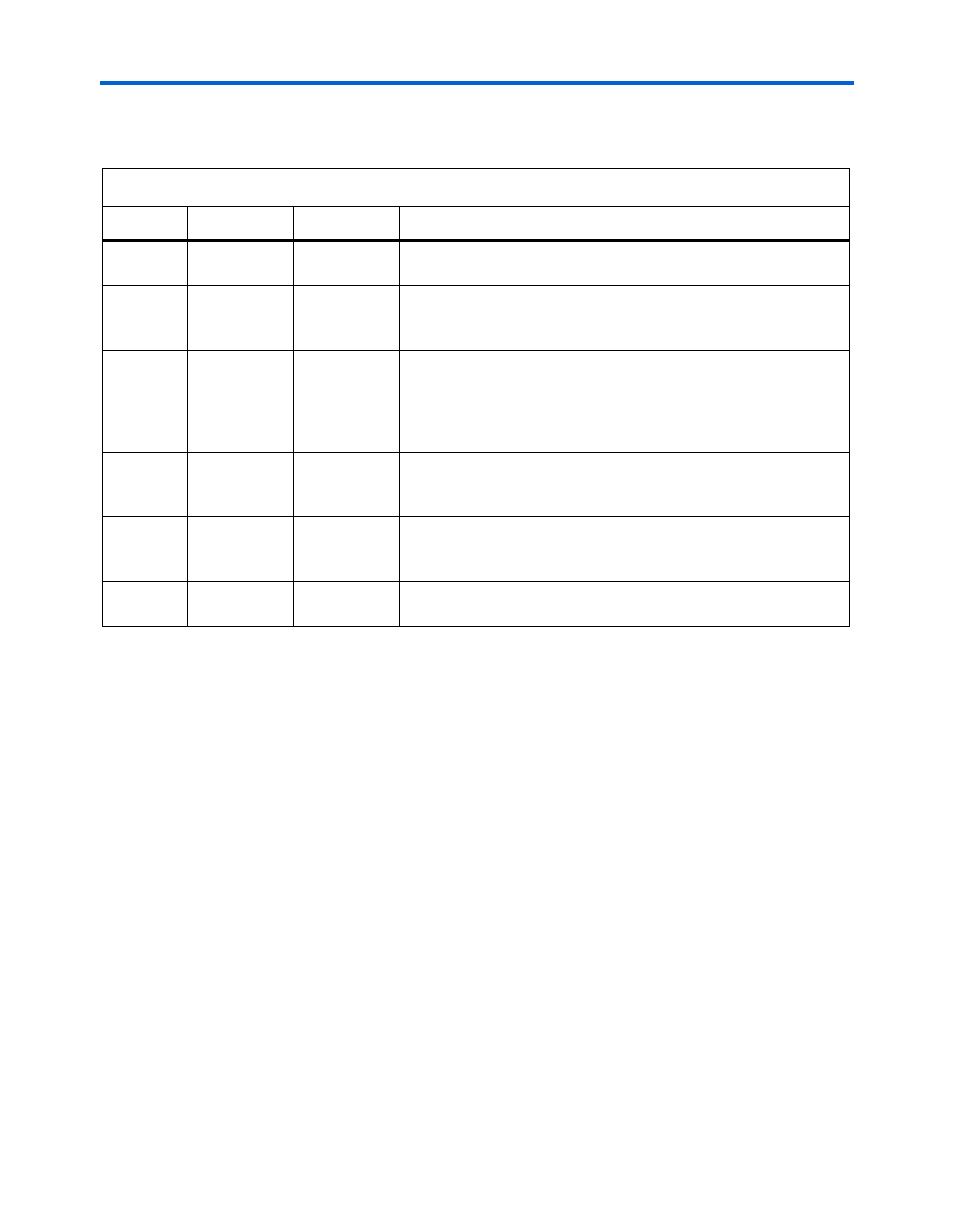
Table 2–19. Configuration Status LED Indicators
LED
Led Name
Color
Description
LED3
Loading
Green
This LED blinks while the configuration controller is actively
transferring data from flash memory into the FPGA.
LED4
Error
Red
If this LED is on, then configuration was not transferred from flash
memory into the FPGA. This can happen if, for example, the flash
memory contains either a valid user or factory configuration.
LED1
User
Green
This LED turns on when the user configuration is being transferred
from flash memory and stays illuminated when the user
configuration data is successfully loaded into the FPGA. If the
FPGA was successfully configured by the EPCS64, LED1 will blink
slowly.
LED2
Factory
Amber
This LED turns on when the factory configuration is being
transferred from flash memory and stays illuminated if the factory
configuration was successfully loaded into the FPGA.
LED6
LED6
Red
This LED is an indicator of the CONFIG_DONE_signal from the
FPGA. This LED illuminates when FPGA configuration completes
successfully and CONFIG_DONE goes high.
LED7
LED7
Red
This LED is an indicator of the flash_CE_n line. It illuminates when
the flash is being accessed and the CE_n line is being asserted.