Expansion prototype connectors (proto1 & proto2) – Altera Nios Development Board Cyclone II Edition User Manual
Page 28
2–16
Reference Manual
Altera Corporation
Nios Development Board Cyclone II Edition
May 2007
Board Components
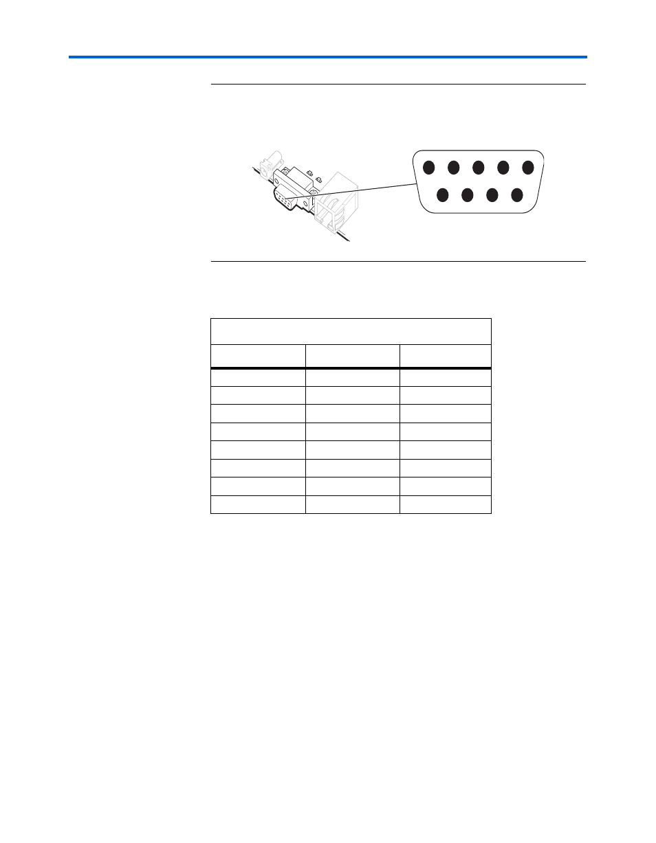
Figure 2–5. Serial Connector J19
Expansion
Prototype
Connectors
(PROTO1 &
PROTO2)
PROTO1 and PROTO2 are standard-footprint, mechanically-stable
connections that can be used (for example) as an interface to a special-
function daughter card. Headers J11, J12, and J13
collectively form
PROTO1, and J15, J16 and J17 collectively form PROTO2.
The expansion prototype connector interface includes:
■
41 I/O pins for prototyping. All 41 I/O pins connect to user I/O pins
on the FPGA. Each signal passes through analog switches to protect
the FPGA from 5V logic levels. These analog switches are
permanently enabled. The output logic-level on the expansion
prototype connector pins is 3.3V.
●
PROTO1 switches: U19, U20, U21, U22 and U25
●
PROTO2 switches: U27, U28, U29, U30 and U31
Table 2–10. Serial Connector Pin Table
FPGA Pin
J19 Pin
Board Net Name
AB15
3
serial_rxd
J22
2
serial_txd
H21
4
serial_dtr
K22
1
serial_dcd
H19
6
serial_dsr
L19
9
serial_ri
L23
8
serial_cts
AC15
7
serial_rts
Function
Direction
Connector Pin #
Connector Pin #
Direction
Function
GND
5
DTR
IN
4
RXD
IN
3
TXD
OUT
2
DCD
OUT
1
9
OUT
RI
8
OUT
CTS
7
IN
RTS
6
OUT
DSR
J19