Configuration controller device (u3), Configuration-status leds, Configuration controller device (u3) –33 – Altera Nios Development Board Cyclone II Edition User Manual
Page 45: Configuration controller
Altera Corporation
Reference Manual
2–33
May 2007
Nios Development Board Cyclone II Edition
Board Components
1
The orientation of J27 is the reverse of J24.
f
See the Serial Configuration Devices chapter in Altera's Configuration
Device Handbook for more information about the EPCS64 device. See the
EPCS Device Controller Core with Avalon Interface chapter in the Quartus II
Handbook, Volume 5: Altera Embedded Peripherals for information about the
EPCS serial flash controller component in SOPC Builder.
Configuration
Controller
Device (U3)
The configuration controller (U3) is an Altera MAX
7000 EPM7256AE
device. It comes preprogrammed with logic for managing board reset
conditions and configuring the FPGA from data stored in flash memory
and the EPCS64 serial configuration device (U69).
FPGA configuration data files are generated by the Quartus II software.
The Nios II integrated development environment (IDE) can write new
configuration data to the board's flash memory.
f
For complete details on the configuration controller connections, see the
board schematic. For detailed information about the Altera EPM7256AE
device, see the MAX 7000 family literature at
www.altera.com/literature/lit-m7k.html.
For details on programming
configuration data to flash memory, see the Nios II Flash Programmer User
Guide, or refer to the Nios II IDE help system.
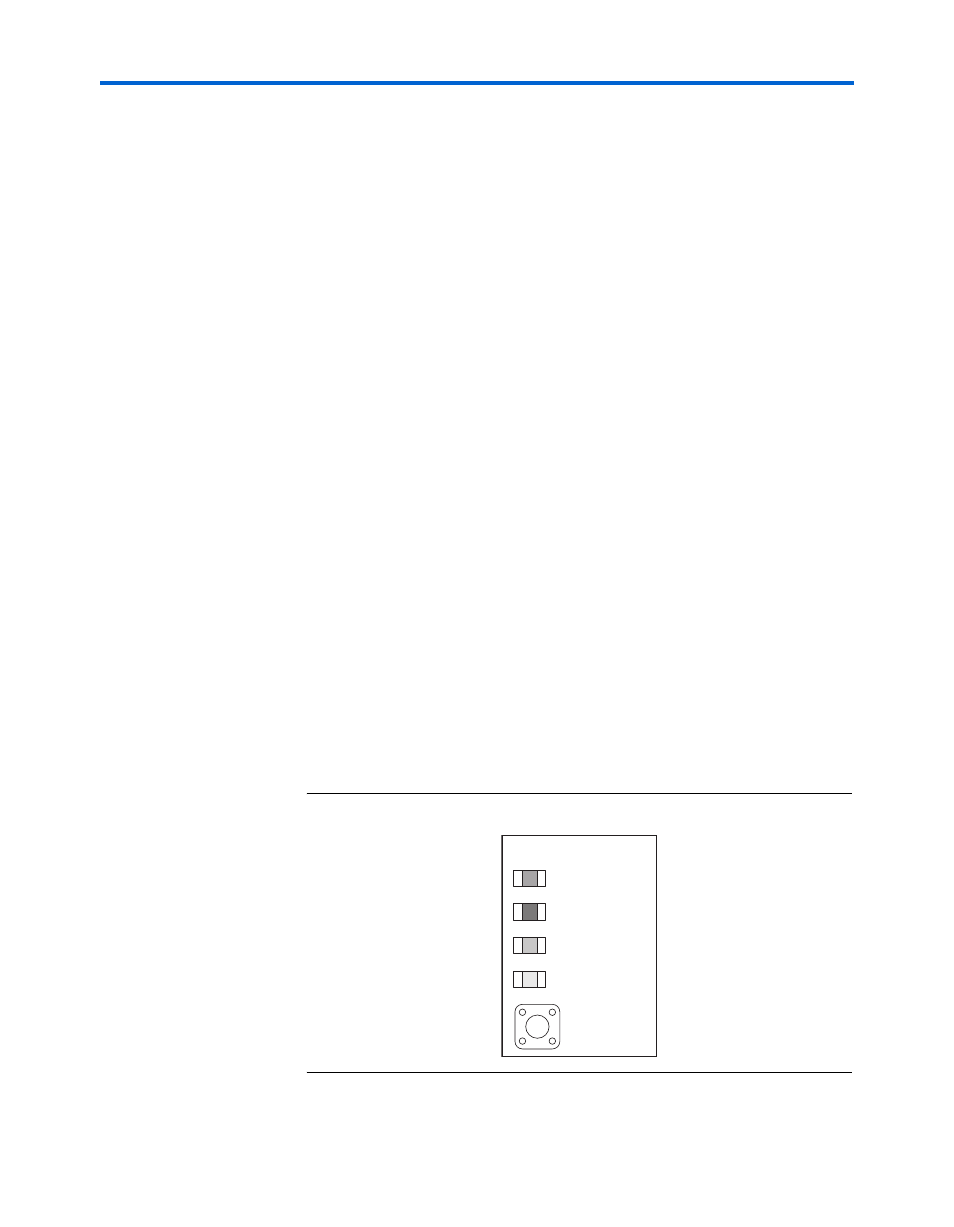
Configuration-Status LEDs
The configuration controller is connected to four status LEDs that show
the configuration status of the board at a glance as shown in
The LEDs indicate which configuration, if any, was loaded into the FPGA
at power-on as shown in
Figure 2–14. LED1 – LED 4
LED 1
LED 2
Factory
Config
Factory
User
Error
Loading
FPGA Config
SW9
LED 4
LED 3