Altera SDI Audio IP Cores User Manual
Page 46
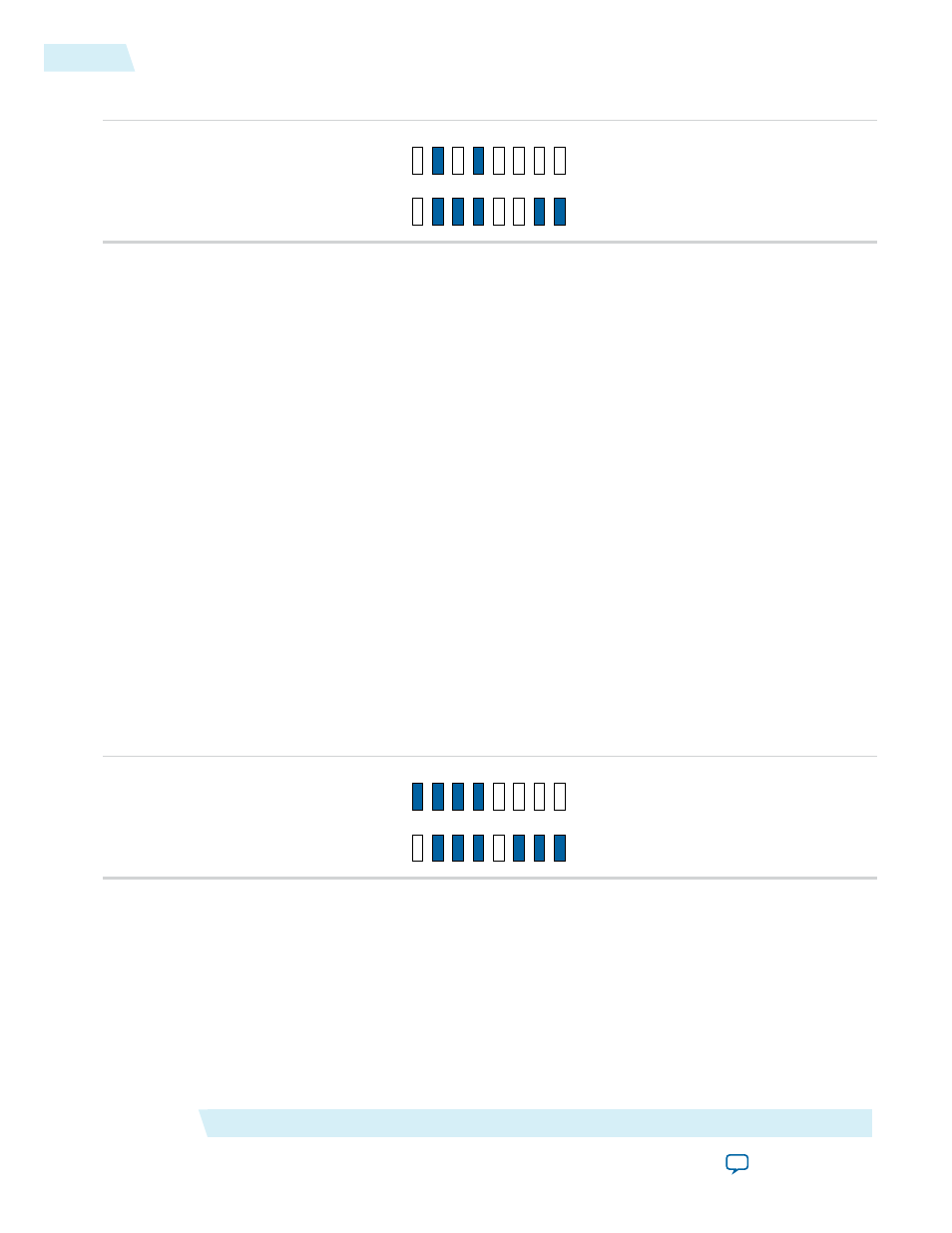
Figure 6-3: Condition of LEDs for Transmitting HDI-SDI Video Standard
D6
D7
D8
D9
D10 D11 D12 D13
D16 D17 D18 D19 D20 D21 D22 D23
3. The external waveform monitor (WFM700) displays the following observation:
a. Colorbar video pattern
b. Video format detected is 1080i 60.00
c. Embedded audio standard detected is SMPTE299M
d. Audio channel pairs (1,2), (3,4), (5,6) and (7,8) are present
Transmit 3G-SDI Level A with Embedding of Audio Group 1, 2 and 3
To transmit the 3G-SDI Level A video standard, follow these steps:
1. Set DIP switch[2:1] = 11
2. The demonstration runs and the LEDs indicate the following conditions:
a. LEDs D6 and D7 indicate the internal video pattern generator signal standard.
b. LEDs D8 and D9 indicate the receive video standard.
c. LED D16 blinks indicating the heartbeat of the receiver's recovered clock..
d. LED D17 illuminates when the receiver is frame locked.
e. LED D18 illuminates when the receiver is TRS locked.
f. LED D19 illuminates when the receiver is alignment locked.
g. LEDs D23, D22 and D21 illuminate when the data packet of audio groups 1, 2 and 3 are detected in
the incoming SDI stream.
This figure shows the condition of the LEDs.
Figure 6-4: Condition of LEDs for Transmitting 3G-SDI Level A Video Standard
D6
D7
D8
D9
D10 D11 D12 D13
D16 D17 D18 D19 D20 D21 D22 D23
Transmit 3G-SDI Level B with Embedding of Audio Group 1, 2, 3 and 4
To transmit the 3G-SDI Level B video standard, follow these steps:
1. Set DIP switch[2:1] = 10
2. The demonstration runs and the LEDs indicate the following conditions:
a. LEDs D6 and D7 indicate the internal video pattern generator signal standard.
b. LEDs D8 and D9 indicate the receive video standard.
c. LED D16 blinks indicating the heartbeat of the receiver's recovered clock.
SDI Audio IP Design Example
Altera Corporation
UG-SDI-AUD
Transmit 3G-SDI Level A with Embedding of Audio Group 1, 2 and 3
6-6
2014.06.30