Sdi audio ip register interface signals, Sdi audio ip register interface signals -10 – Altera SDI Audio IP Cores User Manual
Page 30
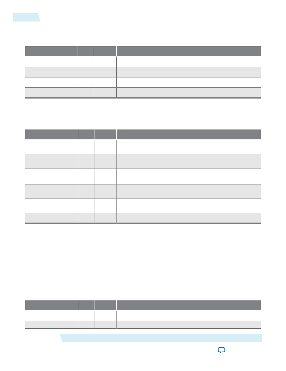
This table lists the input and output signals.
Table 4-15: SDI Audio Clocked Output Input and Output Signals
Description
Direction
Width
Signal
Audio input clock.
Input
[0:0]
aes_clk
Audio data enable.
Output
[0:0]
aes_de
Audio word select.
Output
[0:0]
aes_ws
Audio data input in internal AES format.
Output
[0:0]
aes_data
This table lists the Avalon-ST audio signals when you instantiate the SDI Audio Clocked Output IP core in
Qsys.
Table 4-16: SDI Audio Clocked Output Avalon-ST Audio Signals
Description
Direction
Width
Signal
Clocked audio clock. All the audio input signals are synchronous
to this clock.
Input
[0:0]
aud_clk
Avalon-ST ready signal. Assert this signal when the device is able
to receive data.
Output
[0:0]
aud_ready
Avalon-ST valid signal. The core asserts this signal when it receives
data.
Input
[0:0]
aud_valid
Avalon-ST start of packet signal. The core asserts this signal when
it is starting a new frame.
Input
[0:0]
aud_sop
Avalon-ST end of packet signal. The core asserts this signal when
it is ending a frame.
Input
[0:0]
aud_eop
Avalon-ST data bus. This bus transfers data.
Input
[23:0]
aud_data
Related Information
SDI Audio IP Register Interface Signals
on page 4-10
All SDI Audio IP cores use the same register interface signals.
SDI Audio IP Register Interface Signals
All SDI Audio IP cores use the same register interface signals.
The register interface is a standard 8-bit wide Avalon-MM slave.
Table 4-17: SDI Audio IP Register Interface Signals
Description
Direction
Width
Signal
Clock for the Avalon-MM register interface.
Input
[0:0]
reg_clk
Reset for the Avalon-MM register interface.
Input
[0:0]
reg_reset
SDI Audio IP Interface Signals
Altera Corporation
UG-SDI-AUD
SDI Audio IP Register Interface Signals
4-10
2014.06.30