Transceiver dynamic reconfiguration control logic, Hardware and software requirements, Hardware and software requirements -3 – Altera SDI Audio IP Cores User Manual
Page 43
Transceiver Dynamic Reconfiguration Control Logic
The transceiver dynamic reconfiguration control logic block handles the reconfiguration of the receiver in
the SDI duplex.
Hardware and Software Requirements
The design example requires the following hardware and software:
• Stratix IV GX Audio Video Development Kit—Stratix IV GX FPGA development board and SDI HSMC
• SDI IP Core
• SDI Audio Embed IP Core
• SDI Audio Extract IP Core
• The Quartus II software, version 14.0
Hardware Setup
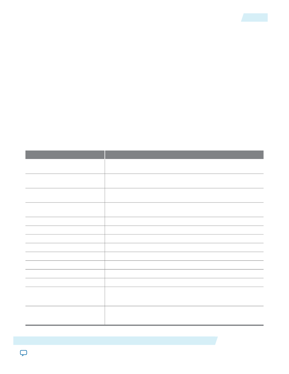
This table lists the function of each LED on the Stratix IV GX FPGA development board.
Table 6-1: Function of Each LED on the Stratix IV GX FPGA Development Board
Description
LED
Indicates the presence of audio group 1 data packet in the incoming
embedded audio.
D23
Indicates the presence of audio group 2 data packet in the incoming
embedded audio.
D22
Indicates the presence of audio group 3 data packet in the incoming
embedded audio.
D21
Indicates the presence of audio group 4 data packet in the incoming
embedded audio.
D20
Indicates that the receiver of the SDI duplex IP Core is alignment locked.
D19
Indicates that the receiver of the SDI duplex IP Core is TRS locked.
D18
Indicates that the receiver of the SDI duplex IP Core is frame locked.
D17
Indicates the recovered clock heartbeat of the receiver.
D16
Indicates the ancillary checksum failure.
D13
Indicates the ancillary parity failure.
D12
Indicates the channel status CRC failure.
D11
Indicates the audio packet failure.
D10
Indicate the SDI receive video standards.
00 = SD-SDI, 01 = HD-SDI, 11 = 3G-SDI Level A, 10 = 3G-SDI Level B
D9–D8
Indicate the SDI transmit video standards.
00 = SD-SDI, 01 = HD-SDI, 11 = 3G-SDI Level A, 10 = 3G-SDI Level B
D7–D6
Altera Corporation
SDI Audio IP Design Example
6-3
Transceiver Dynamic Reconfiguration Control Logic
UG-SDI-AUD
2014.06.30