Sdi audio extract signals, Sdi audio extract signals -5 – Altera SDI Audio IP Cores User Manual
Page 25
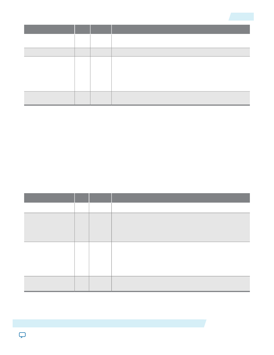
Description
Direction
Width
Signal
This signal does the same function as the sine channel 4 frequency
register.
Input
[7:0]
sine_freq_ch4
Channel status RAM address.
Input
[5:0]
csram_addr
Drive this signal high for a single cycle of
reg_clk
signal to load
the value of the
csram_data
port into the channel status RAM at
the address on the
csram_addr
port.
If each input audio pair gets separate channel status RAMs, this
signal addresses the RAM selected by the
extended_control
port.
Input
[0:0]
csram_we
Channel status data. This signal does the same function as the
channel status RAM register in Table 4–9.
Input
[7:0]
csram_data
Related Information
•
on page 5-1
•
SDI Audio IP Register Interface Signals
on page 4-10
All SDI Audio IP cores use the same register interface signals.
SDI Audio Extract Signals
The following tables list the signals for the SDI Audio Extract IP core.
This table lists the clock recovery input and output signals.
Table 4-7: SDI Audio Extract Recovery Input and Output Signals
Description
Direction
Width
Signal
This signal resets the system.
Input
[0:0]
reset
Assert this 200 MHz reference clock when you turn on the Include
Clock parameter.
If you do not turn on the Include Clock parameter, tie this signal
low.
Input
[0:0]
fix_clk
The core asserts this 64 × sample rate clock (3.072 MHz audio
clock) when you turn on the Include Clock parameter. You use
this clock to clock the audio interface in synchronous mode.
As the core creates this clock digitally, it is prone to higher levels
of jitter.
Output
[0:0]
aud_clk_out
The core asserts this sample rate clock when you turn on the
Include Clock parameter.
Output
[0:0]
aud_clk48_out
This table lists the video input signals.
Altera Corporation
SDI Audio IP Interface Signals
4-5
SDI Audio Extract Signals
UG-SDI-AUD
2014.06.30