Running the design example, Running the design example -4 – Altera SDI Audio IP Cores User Manual
Page 44
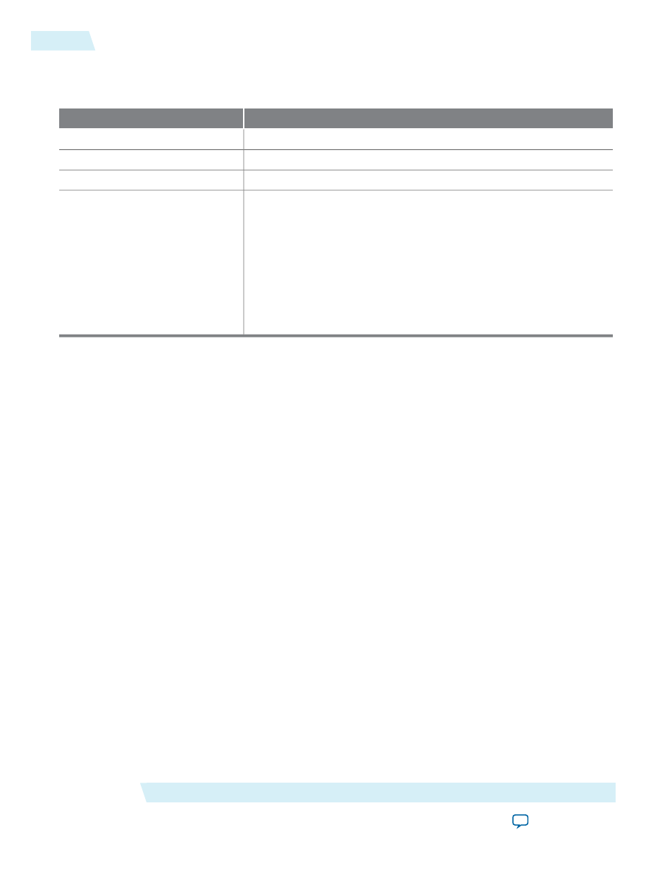
This table lists the function of each user-defined dual in-line package (DIP) switch settings.
Table 6-2: Function of Each DIP Switch
Description
DIP Switch
Resets the system.
8
Resets the Audio Extract IP core status registers.
7
Unused.
6–3
Configure the internally-generated video standards for both SDI
transmitters.
00 = SD-SDI: When 00, enables the embedding of audio group 1,
01 = HD-SDI: When 01, enables the embedding of audio group 1 and 2,
11 = 3G-SDI Level A: When 11, enables the embedding of audio group
1, 2, and 3,
10 = 3G-SDI Level B: When 10, enables the embedding of audio group
1, 2, 3, and 4
2–1
Related Information
For information about how the Stratix IV GX FPGA development board connects to the SDI HSMC.
Running the Design Example
To run the design example, you must set up the development board.
To set up the development board, follow these steps:
1. Set up the board connections.
a. Connect the SDI HSMC to HSMA port on the Stratix IV GX development board.
b. Connect the development board to the power supply.
c. Connect the
SDI_OUT_2
port (SDI TX P0) to the
SDI_IN_1
port (SDI duplex) using external BNC
cable.
d. Connect the
AES_OUT_1
port to the
AES_IN_1
port using external BNC cable.
e. Connect the
SDI_OUT_1
port (SDI duplex) to the external waveform monitor so that you can analyze
the embedded audio in the SDI video stream.
2. Launch the Quartus II software.
a. On the File menu, click Open Project, navigate to
ip/altera/audio_ip/example/s4gx_sdi_audio/s4gxsdi_
audio.qpf
, and click Open.
b. On the Processing menu, click Start Compilation.
3. Download the Quartus II-generated SRAM Object File (
.sof
).
After you set up the board, run the different configurations described in the following sections.
SDI Audio IP Design Example
Altera Corporation
UG-SDI-AUD
Running the Design Example
6-4
2014.06.30