Altera SDI Audio IP Cores User Manual
Page 22
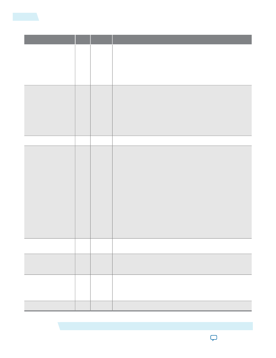
Table 4-2: SDI Audio Embed Video Input and Output Signals
Description
Direction
Width
Signal
The video clock that is typically 27 MHz for SD-SDI, 74.25 MHz
or 74.17 MHz for HD-SDI, or 148.5 MHz or 148.35 MHz for 3G-
SDI standards. You can use higher clock rates with the
vid_
datavalid
signal.
Set exclusive clock group to
aud_clk
and
vid_clk
to prevent
unstable or flickering image.
Input
[0:0]
vid_clk
Indicates the received video standard. Applicable for 3G-SDI, dual
standard, and triple standard modes only.
Set this signal to indicate the following formats:
• [00] for10-bit SD-SDI
• [01] for 20-bit HD-SDI
• [10] for 3G-SDI Level B
• [11] for 3G-SDI Level A
Input
[1:0]
vid_std
Assert this signal when the video data is valid.
Input
[0:0]
vid_datavalid
Receiver protocol reset signal. This signal must be driven by the
rx_rst_proto_out
reset signal from the transceiver block.
This signal carries luma and chroma information.
SD-SDI:
• [19:10] Unused
• [9:0] Cb,Y, Cr, Y multiplex
HD-SDI and 3G-SDI Level A:
• [19:10] Y
• [9:0] C
3G-SDI Level B:
• [19:10] Cb,Y, Cr, Y multiplex (link A)
• [9:0] Cb,Y, Cr, Y multiplex (link B)
Input
[19:0]
vid_data
The core drives this signal high during valid output video clock
cycles.
Output
[0:0]
vid_out_datavalid
The core drives this signal high during the first 3FF clock cycle of
a video timing reference signal; the first two 3FF cycles for 3G-SDI
Level B. This signal provides easy connection to the SDI IP cores.
Output
[0:0]
vid_out_trs
The video line signal that provides for easy connection to the SDI
IP cores. To observe the correct video out line number, allow two-
frame duration for the audio embed IP to correctly embed and
show the line number.
Output
[10:0]
vid_out_ln
The video output signal.
Output
[19:0]
vid_out_data
SDI Audio IP Interface Signals
Altera Corporation
UG-SDI-AUD
SDI Audio Embed Signals
4-2
2014.06.30