Sdi clocked audio input registers, Sdi clocked audio input registers -8 – Altera SDI Audio IP Cores User Manual
Page 39
Clock Status Register
To create a 48-kHz signal synchronous to the video clock,
you must detect whether a 1 or 1/1.001 video clock rate is
used. If you detect a 1/1.001 video clock rate, this field
returns high.
RO
74.17-MHz video clock
7
Channel Status RAM
Read accesses within the address range 10h to 3Fh to the
channel status RAM. This field returns the 24 bytes of
channel status for X channel starting at address 10h, and
the 24 bytes of channel status for Y channel starting at
address 28h.
WO
Channel status data
7:0
SDI Clocked Audio Input Registers
The following tables list the registers for the SDI Clocked Audio Input IP core.
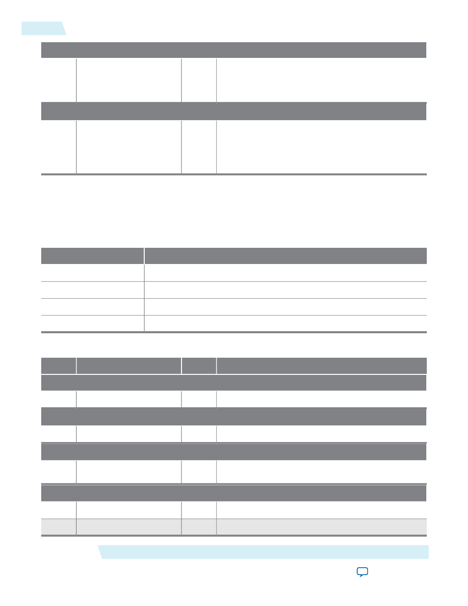
Table 5-5: SDI Clocked Audio Input Register Map
Name
Bytes Offset
Channel 0 Register
00h
Channel 1 Register
01h
FIFO Status Register
02h
FIFO Reset Register
03h
Table 5-6: SDI Clocked Audio Input Registers
Description
Access
Name
Bit
Channel 0 Register
The user-defined channel number of audio channel 0.
RW
Channel 0
7:0
Channel 1 Register
The user-defined channel number of audio channel 1.
RW
Channel status RAM select
7:0
FIFO Status Register
This sticky bit reports the overflow of the clocked audio
input FIFO.
RO
Active channel
7:0
FIFO Reset Register
Reserved for future use.
WO
Unused
6:0
Resets the clocked audio FIFO.
WO
FIFO reset
7
SDI Audio IP Registers
Altera Corporation
UG-SDI-AUD
SDI Clocked Audio Input Registers
5-8
2014.06.30