Power-on button fan interfaces, Table 3-19, Table 3-20 – ADLINK ReadyBoard 910 User Manual
Page 43: Cpu fan interface pin signal descriptions (fn1), Table 3-21, System fan interface pin signal descriptions (fn2)
Chapter 3
Hardware
ReadyBoard 910
Reference Manual
37
Power-On Button
The Power-On button turns the ReadyBoard 910 and its attached power supply to a fully on condition, if you
are using an ATX power supply. Normally—if the operating system (OS) supports sleep states—the OS will
turn off the ReadyBoard 910 and its power supply during the OS shut down process. If the OS supports sleep
states, the Power-On button will also transition the ReadyBoard and its power supply between a fully
Powered-On state, various sleep states depending on the OS control setting, and a fully Powered-Off state. If
the OS does not support sleep states, then the Power-On button only turns on or off power to the
ReadyBoard 910.
The sleep states are OS dependent and not available if your OS does not support power management based
on the ACPI standard. An OS supporting ACPI will allow the Power-On button to be configured through a
user interface.
The Power-On button is provided externally by connecting a momentary button to the Power-On button
header (JP6). See
Fan Interfaces
The ReadyBoard 910 provides two headers for system and CPU fans, as required.
define the pin signals for the CPU and System fan interfaces, which provide single-row, 3-pin headers with
0.100" (2.54 mm) pitch.
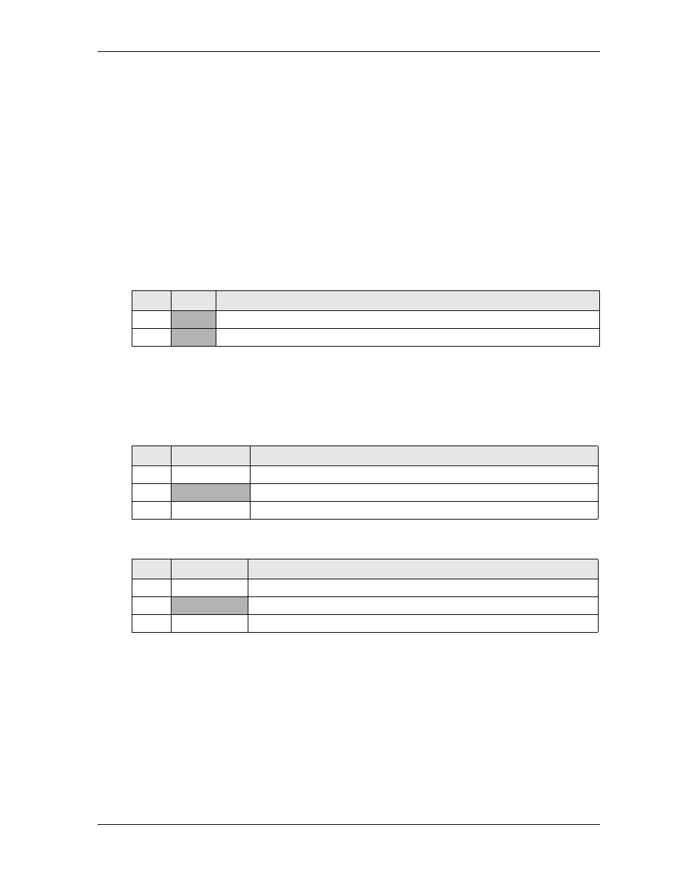
Note: The shaded table cells denote power or ground.
Table 3-19. Power-On Button Interface Pin Signal Descriptions (JP6)
Pin #
Signal
Description
1
+3.3
+3.3 volts DC +/- 5%
2
GND Ground
Table 3-20. CPU Fan Interface Pin Signal Descriptions (FN1)
Pin #
Signal
Description
1
FAN1_TACH
Fan Speed Detect – This is the fan speed tachometer signal.
2
+12
+12 volts DC +/- 5%
3
FN1_PWM
Modulation – This signal controls the fan speed.
Table 3-21. System Fan Interface Pin Signal Descriptions (FN2)
Pin #
Signal
Description
1
FAN2_TACH
Fan Speed Detect – This is the fan speed tachometer signal.
2
+12
+12 volts DC +/- 5%
3
FN2_PWM
Modulation – This signal controls the fan speed.