Block diagram, Figure 2-3, Functional block diagram – ADLINK ReadyBoard 910 User Manual
Page 14: 8reference manual readyboard 910, Figure 2-3. functional block diagram
Chapter 2
Product Overview
8
Reference Manual
ReadyBoard 910
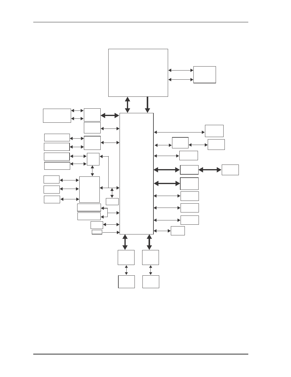
Block Diagram
illustrates the functional components of the ReadyBoard 910.
Figure 2-3. Functional Block Diagram
CPU
Intel
Core i7-3610QE (Quad-Core) 2.3GHz
Core i5-3610ME (Dual-Core) 2.7GHz
Core i3-3120ME (Dual-Core) 2.2GHz
Core i7-2710QE (Quad-Core) 2.1GHz
Core i5-2510E (Dual-Core) 2.5GHz
Core i3-2330E (Dual-Core) 2.2GHz
Celeron B810 (Dual-Core) 1.6GHz
(with integrated Processor Core
and Graphics Memory Hub)
DDR3
SODIMM
Sockets (2)
FDI
DMI
1067/1333MHz,
1.5V, 16GB Max.
PCH
Intel
BD82HM65
GLAN
Intel
82574IT
Controller
GLAN2
RJ45
Connector
PCIe X1, Port 2
PCIe X1,
Port 1
USB 1-2
(2.0)
HD Audio
PCIe X1, Port 5
PCIe X1,
Port 4
SATA 3.0, Port 1
SATA 3.0, Port 2
SATA 2.0, Port 3
32-bit PCI
COM0
COM1
PS/2 KB+MS
SPI
BIOS
Debug
Header
VGA
VGA
DB15
Connector
DVI
Connector
PCI-104
Connector
Level
Shifter
TMDS
24-bit LVDS
TMDS/DVI
LVDS
Connector
SATA
Connector
SATA
Connector
SSD
PCIe-to-PCI
Bridge
PCIe
Mini Card
Connector
USB 3.0
Host
USB 2.0
Header
HDA
Codec
GPIO
GPIO
Header
EXT
Header
Channel - A
Channel - B
SMBus
LPC
LPC
COM2
CAN
USB 2
USB 1
COM2-3
(only
TX/RX)
SMBus DATA
Header
SMBus CLOCK
Header
DB9
Connector
10-Pin
Header
Mini-DIN
Connector
Telecom Module
(Optional)
CAN Module
(Optional)
USB 3.0 Dual Port
Connector
Super I/O
SCH3114-NU
S/PDIF Audio
Header
Audio
Header
VBAT
Battery
Header
GLAN
Intel
82574IT
Controller
GLAN1
RJ45
Connector
PCIe X1,
Port 3
RB910_blk_diag_b