Figure 3-1, Rs-485 serial port implementation, Table 3-4 – ADLINK ReadyBoard 910 User Manual
Page 32: Serial port 2 (cn8) interface pin signals
Chapter 3
Hardware
26
Reference Manual
ReadyBoard 910
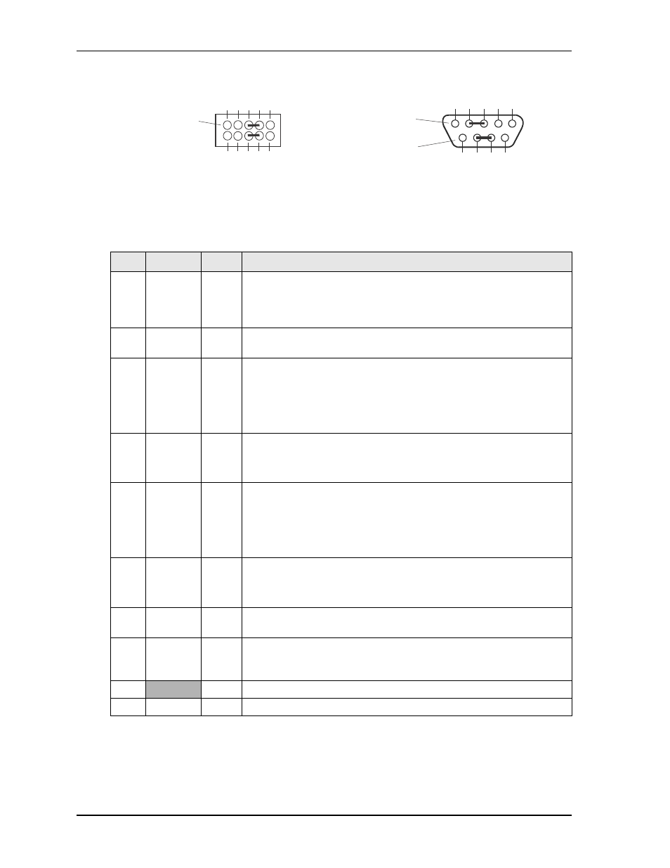
The RS-422 mode uses a four-wire interface and does not need any pins tied together, but you must select
RS-485 mode in BIOS Setup.
Figure 3-1. RS-485 Serial Port Implementation
provides the signals for the corresponding pins of the serial 2 interface (CN8). The serial 2
interfaces provides a 10-pin, header with 2 rows, odd/even sequence (1, 2), and 0.079" (2mm) pitch.
Note: The shaded table cells denote power or ground. Signals appear in the second column as RS-232
followed by RS-485/RS-422. The * symbol indicates the signal is Active Low.
Table 3-4. Serial Port 2 (CN8) Interface Pin Signals
Pin # Signal
DB9 # Description
1
DCD*
1
Data Carrier Detect – Indicates external serial device is detecting a
carrier signal (i.e., a communication channel is currently open). In direct
connect environments, this input is driven by DTR as part of the DTR/
DSR handshake.
2
DSR*
6
Data Set Ready – Indicates external serial device is powered, initialized,
and ready. Used as hardware handshake with DTR for overall readiness.
3
RXD
Rx Data –
2
Receive Data – Serial port receive data input is typically held at a logic 1
(mark) when no data is being transmitted, and is held “Off” for a brief
interval after an “On” to “Off” transition on the RTS line to allow the
transmission to complete.
Serial Port 1 or 2 – If in RS-485 mode, this pin is Rx Data Negative.
4
RTS*
Tx Data +
7
Request To Send – Indicates serial port is ready to transmit data. Used as
hardware handshake with CTS for low level flow control.
Serial Port 1 or 2 – If in RS-485 mode, this pin is Tx Data Positive.
5
TXD
Tx Data –
3
Transmit Data – Serial port transmit data output is typically held to a
logic 1 when no data is being sent. Typically, a logic 0 (On) must be
present on RTS, CTS, DSR, and DTR before data can be transmitted on
this line.
Serial Port 1 or 2 – If in RS-485 mode, this pin is Tx Data Negative.
6
CTS*
Rx Data +
8
Clear To Send – Indicates external serial device is ready to receive data.
Used as hardware handshake with RTS for low level flow control.
Serial Port 1 or 2 – If in RS-485 mode, this pin is Rx Data Positive.
7
DTR*
4
Data Terminal Ready – Indicates serial port is powered, initialized, and
ready. Used as hardware handshake with DSR for overall readiness.
8
RI*
9
Ring Indicator – Indicates external serial device is detecting a ring
condition. Used by software to initiate operations to answer and open the
communications channel.
9
GND
5
Ground
10
Key/NC
NC
Key Pin/Not connected
RB910RS485jump_a
Or
1
3
5
7
9
2
4
6
8
10
Serial Port 2
(CN8, COM1)
Standard DB9
Serial Port 1
(CN17, COM0)
Connector (Male)
Front View
5
4
3
2
1
9
8
7
6