Table 3-12, Table 3-13, User gpio signals pin/signal descriptions (cn13) – ADLINK ReadyBoard 910 User Manual
Page 39
Chapter 3
Hardware
ReadyBoard 910
Reference Manual
33
External Beeper/Buzzer Interface
The Beeper/Buzzer signals from the PCH are fed to Beeper/Buzzer header through an OR circuit in
conjunction with +5V to drive an external PC speaker. The signal is also fed to the on-board Audio CODEC
to provide a PC Beep/Buzz signal for the Line Out connections.
Note: The shaded table cell denotes power.
System Reset Switch
This momentary push-button switch (SW2) invokes a hard reset.
Temperature Monitoring
The Super I/O controller performs the temperature monitoring function. The board temperatures can be
monitored from the Hardware Monitor feature in the Advanced BIOS setup screen.
User GPIO Signals
The ReadyBoard 910 provides eight GPIO pins for custom use. The signals are routed to the CN13 header,
and the enable and initialize values are set in the BIOS.
For more information about GPIO pin operation, refer to the Programming Manual for the Super I/O
controller at:
http://www.smsc.com/main/catalog/sch311x.html
describes the pin signals of the GPIO interface, which provides a 10-pin header of two rows with
odd/even (1,2) pin sequence and 0.079" (2mm) pitch.
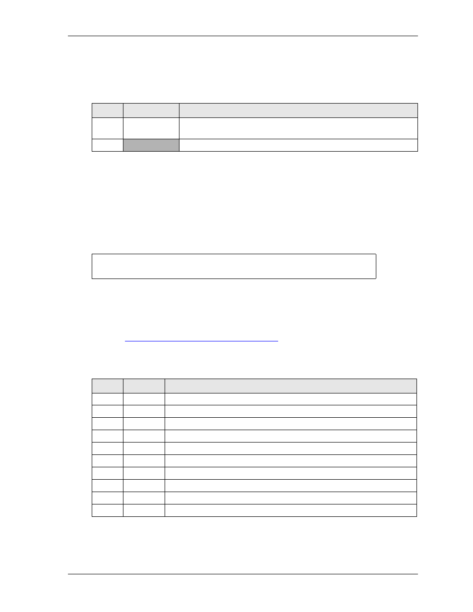
Table 3-12. External Beeper/Buzzer Interface Pin Signal Descriptions (JP5)
Pin #
Signal
Description
1
BUZZ_BEEP
Speaker Output – This signal drives an external PC Beeper/Buzzer
speaker.
2
P5V_S
+5 Volt Standby
NOTE
The ReadyBoard 910 requires an active heatsink (with fan) for the CPU and a
passive heatsink (without fan) for the PCH.
Table 3-13. User GPIO Signals Pin/Signal Descriptions (CN13)
Pin #
Signal
Description
1
GPI0
User defined
2
GPO0
User defined
3
GPI1
User defined
4
GPO1
User defined
5
GPI2
User defined
6
GPO2
User defined
7
GPI3
User defined
8
GPO3
User defined
9
NC
Not Connected
10
NC
Not Connected